06/2016 - Art. Nr. 4200 1041 1103A 9
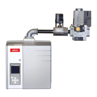
Operation
Control and safety unit BT 3xx gas operation
Legend to the sequence diagram
t1 Awaiting boiler safety circuit
Air pressure switch min. request
t2 Time for pressure build-up in the gas control line (only
when sealing test mode is activated, program sequence
for density test can vary, see sequence diagram for
density test)
t3 Servomotor running time
t4 Closing of gas flap
t5 Ventilation time
t6 Transformer activation time
t9 Safety time
t10 Operating phase
t11 Regulation
t12 Time for pressure release in the gas control line
t13 Postventilation time
t14 Servomotors under base load
t15 Post combustion time
t16 Flame extinction test
t17 Sealing test gas valve 2
Sealing test sequence diagram -
no gas pressure at start of sealing test.
Sealing test sequence diagram - gas pressure present at start of
sealing test.
Legend to the sequence diagrams
t1 Ventilation time, always 2 seconds
t2 Delay time, always 2 seconds
t3 Sealing test time, configurable
t4 Filling time, configurable
The diagrams on this page have been taken from the operating instructions of the BurnerTronic BT300 BT320 BT340 from Lamtec.
Print no. DLT1200-11-aDE-002 Copyright© 2011 LAMTEC
Boiler safety circuit
Gas safety circuit
Burner on
Minimum gas pressure switch
Air pressure switch
Flame signal
Air flap
Gas flap
Ignition transformer
Gas valve 1
Gas valve 2
Air motor
Fault
 Loading...