06/2016 - Art. Nr. 4200 1041 1103A 7
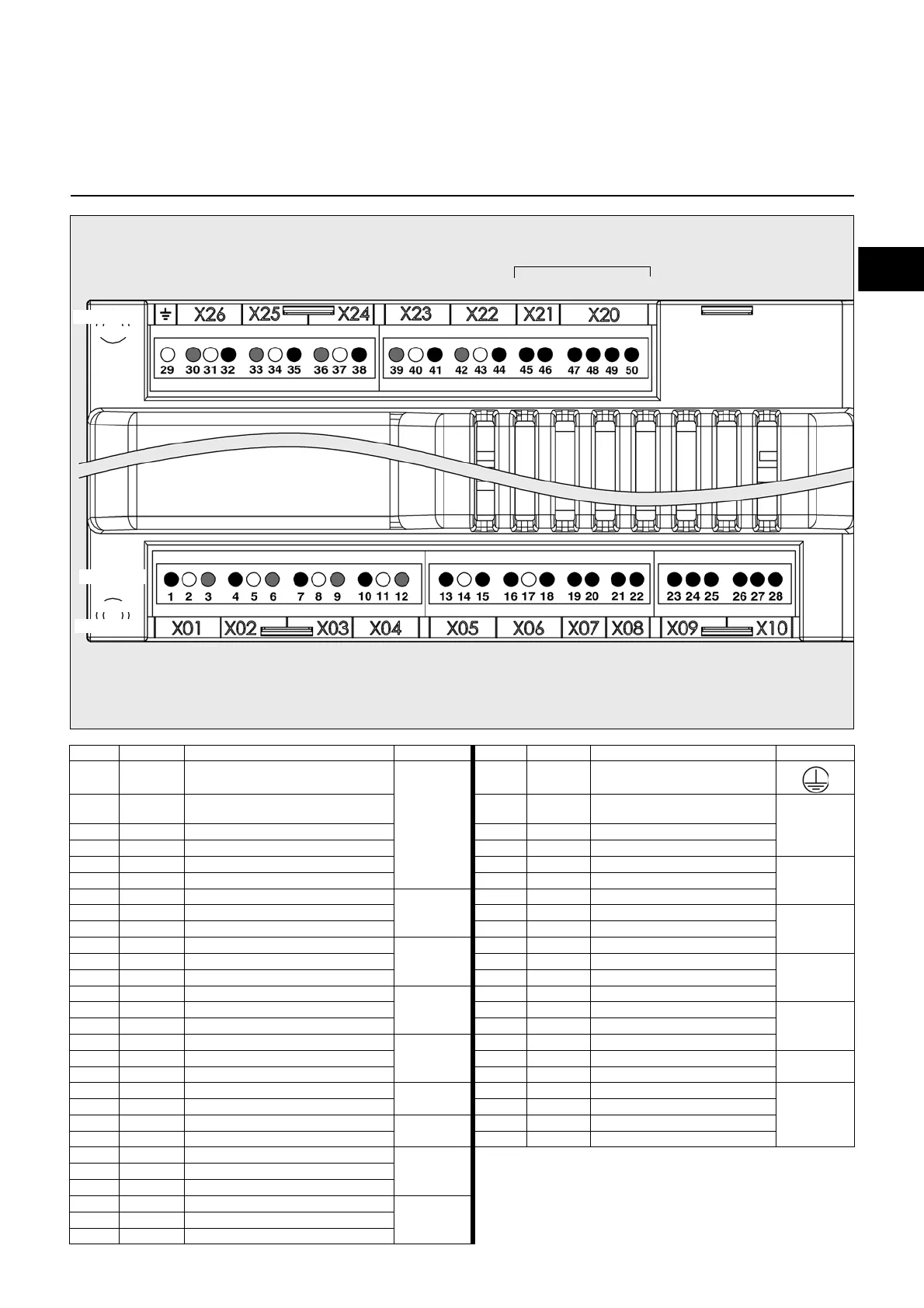
Pin Terminal Description Connector Pin Terminal Description Connector
1 1 Phase gas solenoid valve 1
X01
+
X02
1 29 Grounding of the burner
2 2 Earth 1 30 Neutral conductor of the fuel-oil
pump
X26
3 3 Neutral conductor 2 31 Earth
1 4 Phase gas solenoid valve 2 3 32 Phase
2 5 Neutral conductor 1 33 Neutral conductor
X25
3 6 Earth 2 34 Earth
1 7 Phase fuel valve 3 (optional)
X03
3 35 Phase burner motor
2 8 Earth 1 36 Neutral conductor
X24
3 9 Neutral conductor 2 37 Earth
1 10 Phase ignition transformer
X04
3 38 Alarm output
2 11 Earth 1 39 Neutral conductor
X23
3 12 Neutral conductor 2 40 Earth
1 13 Phase gas pressure switch min.
X05
3 41 L1 power supply
2 14 Earth 1 42 Neutral conductor
X22
3 15 Phase 2 43 Earth
1 16 Phase burner safety circuit
X06
3 44 L1 power supply output
2 17 Earth 1 45 UV flame monitor (-)
X21
3 18 Phase 2 46 UV flame monitor (+)
1 19 Phase boiler safety circuit
X07
1 47 Ionisation probe
X20
2 20 Phase 2 48 Phase
1 21 Phase air pressure switch
X08
3 49 Flame monitor (+)
2 22 Phase 4 50 Flame monitor (-)
1 23 Load (-)
X09
2 24 Load (+)
3 25 Phase
1 26 Malfunction reset
X10
2 27 Burner ON
3 28 Phase
Operation
Terminal allocation chart
Air
pressure
switch
Ignition
device
Terminal
Connector
Remote
unlocking
Solenoid
valves
(1+2)
Heating
request
Min. gas
pressure
Burner
safety
circuit
Boiler
safety
circuit
Solenoid
valve 3
Flame check
Fault
display
Burner motor
Terminal
L1 power supply
Grounding of
the burner
UV detector
L1 auxiliary power
supply
Ionisation
Flame
detector
Connector
1 3 2 1 3 2 1 3 2 1 3 2 1 3 2 1 2 1 4 3 2 1
1 2 3
1 2 3
1 2 3
Pin
Pin
1 2 3 1 2 3
1 2 3
1 2 3 1 2 3 1 2
1 2
 Loading...