06/2016 - Art. Nr. 4200 1041 1103A 17
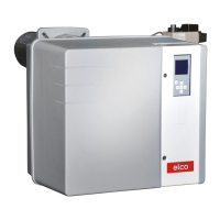
Installation
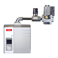
Gas train
Accessories (for PED option)
Gas train installation
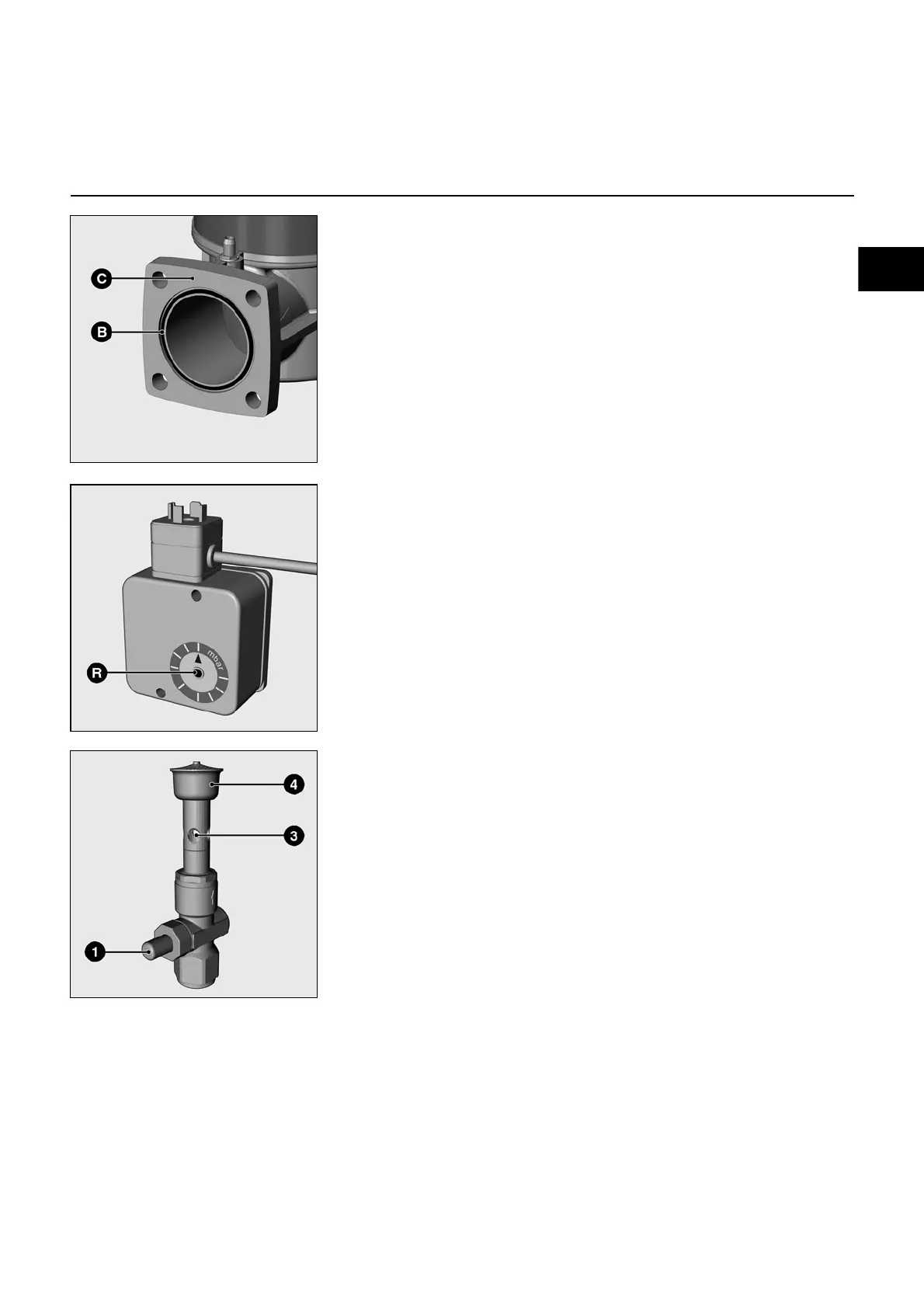
• Check the correct position of the
O-ring B in the gas connecting
flange C.
• Secure the gas train with M10 nuts so
that the SKP regulator or the coils of
the MBC-SE are positioned
perpendicular to the gas train.
• Pay attention to the direction of
circulation.
• Connect the power cable to the gas
train.
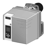
Test burner
Depending on the country-specific
requirements, when installing steam
boilers it may be necessary to fit a test
burner to the gas train (e.g. in line with
the Pressure Equipment directive TRD
412). This is used to vent the gas control
system.
The gas supply is switched on by
pressing the button (1). The flow of gas
brings in the required amount of
combustion air via the hole in the burner
tube (3). The gas/air mixture is routed
towards the burner head (4) and ignited
manually at its opening. Gas is supplied
for as long as the button is pressed and
cut off when it is released.
Technical data:
• Type of gas:
gases in accordance with DVGW
worksheet G 260/1, gas families 1, 2, 3
• Ambient temp.: -15°C to +70°C
• Installation position: vertical, facing
upwards
• Operating pressure to: 500 mbar
NEW IMAGE
y403899.jpg
NEW IMAGE
y403899.jpg
NEW IMAGE
y403899.jpg
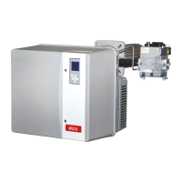
Max. gas pressure switch
The gas pressure switch is used to
control gas pressure. The pressure
switch is installed here in order to
monitor pressure increase (maximum
value recommended for installations
implemented according to standard
TRD 604).
The setpoint (switching point) is set on a
rotary scale.
 Loading...