06/2016 - Art. Nr. 4200 1041 1103A16
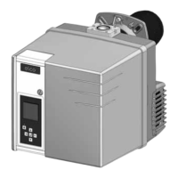
Ø a Ø b c d
195 220-260 M10 45°
Installation
Burner installation
Preparing the boiler front
• Prepare the burner mounting plate/
boiler door in accordance with the
diagram.
• Establish the internal diameter a of
195 mm.
• To mount the burner head bracket,
drill four M10 holes (drill diameter 220
to 260 mm) as shown in the diagram
opposite.
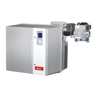
Burner head assembly
• Screw the bolts into the burner fixing
plate/boiler door and position the
insulating seal. For a drill hole of
< 260 mm, the elongated slots in the
gasket should be cut to the required
dimensions.
• Remove the combustion components
from the head.
• Attach the burner head with 4 nuts
(ref. 4). At this point, check that the
gas connection flange is correctly
positioned (on the left or right).
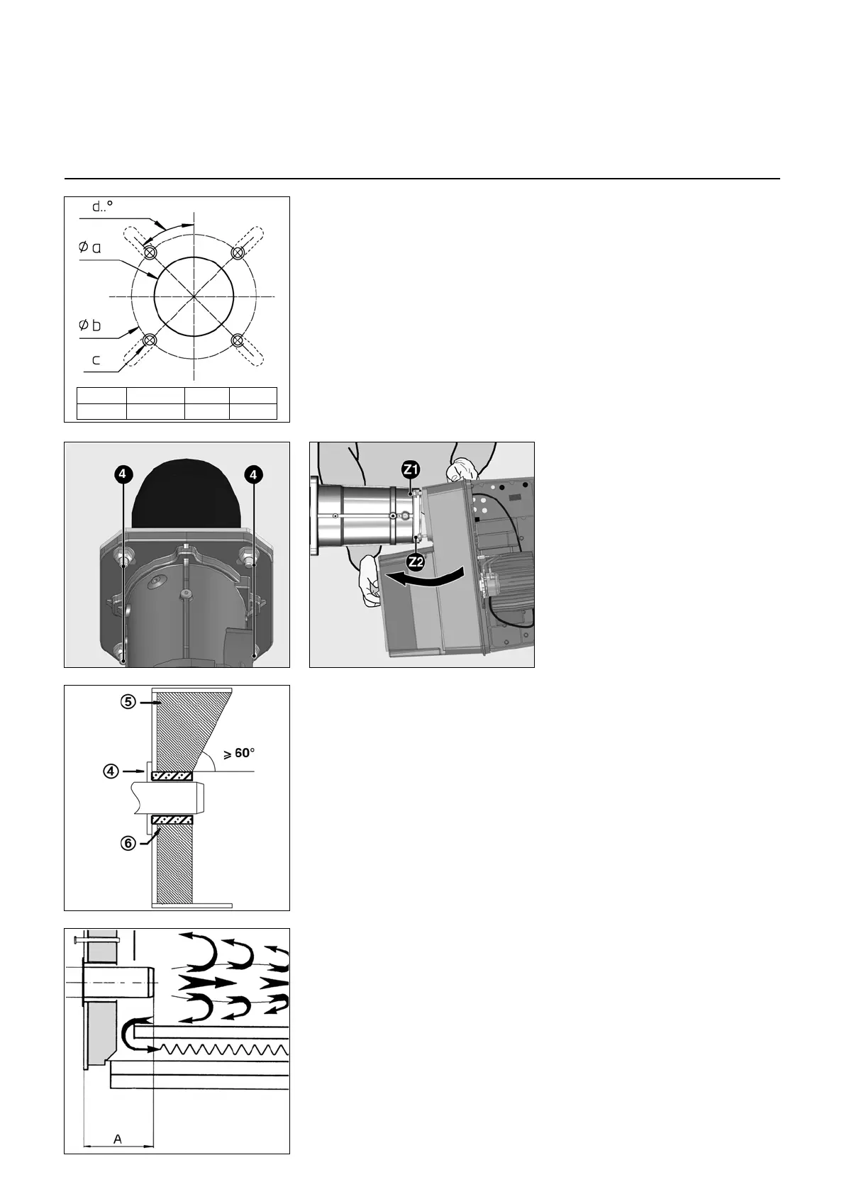
Burner tube installation depth and
brickwork surround
Unless otherwise specified by the boiler
manufacturer, heat generators without a
cooled front wall require brickwork or
insulation 5 as shown in the illustration
opposite. The brickwork must not
protrude beyond the leading edge of the
flame tube, and should have a maximum
conical angle of 60°. Space 6 must be
filled with an elastic, non-flammable
insulation material.
The furnace pressure take-off pipe pF
must not be clogged.
Exhaust gas evacuation system
To avoid unpleasant noise emissions,
right-angled connectors should not be
used on the flue gas side of the boiler.
On boilers with reverse firing, the
minimum flame tube insertion depth A
should be observed as per the boiler
manufacturer's instructions.
Fitting the burner body
• On the burner body, fully unscrew the
two upper nuts Z1 and remove the two
lower nuts Z2.
• Place the burner housing sloping
diagonally forwards and fit the two upper
bolts into the two slots in the burner
attachment head.
• Rest the burner body on the spacer and
tighten the four nuts.
• If necessary, the body can be fitted with
the volute casing upwards. In this case,
proceed in the opposite direction to
fitting.
The body cannot be positioned in any
other way.
For assembly in the position with
the volute facing upwards, unclip
the display, turn it over 180°, and
refit it.
 Loading...