06/2016 - Art. Nr. 4200 1041 1103A20
Installation
Electrical connection
Checks before commissioning
Checks before commissioning
The following must be checked before
initial commissioning:
• That the burner is assembled in
accordance with the instructions given
here.
• That the burner is pre-set in
accordance with the values in the
adjustment table.
• Setting the combustion components.
• The heat generator must be ready for
operation, and the operating
regulations for the heat generator
must be observed.
• All electrical connections must be
correct.
• The heat generator and heating
system must be filled with water and
the circulating pumps must be in
operation.
• The temperature regulator, pressure
regulator, low water detectors and any
other safety or limiting devices that
might be fitted must be connected and
operational.
• The exhaust gas duct must be
unobstructed and the secondary air
system, if available, must be
operational.
• An adequate supply of fresh air must
be guaranteed.
• The heating request must be
available.
• Sufficient gas pressure must be
available.
• The fuel supply lines must be
assembled correctly, checked for
leaks and bled.
• A standard-compliant measuring point
must be available, the exhaust gas
duct up to the measuring point must
be free of leaks to prevent anomalies
in the measurement results.
General regulations applying to the
gas connection
• The gas train must only be connected
to the gas mains by a recognised
specialist.
• The cross-section of the gas line
should be of a size designed to
guarantee that the gas flow pressure
does not drop below the specified
level.
• A manual shut-off valve (not supplied)
must be fitted upstream of the gas
train.
• In Germany, a thermally triggered
shut-off valve (to be installed by the
customer side) must be fitted as
specified by the draft combustion
ordinance.
It is the responsibility of the fitter or his
representative to obtain approval for the
system at the same time as the burner is
commissioned. Only the fitter or his
representative can guarantee that the
system meets applicable standards and
regulations. The fitter should be in
possession of the corresponding official
permit, and should carry out the
corresponding sealing tests and purge
the system of air.
All electrical installation and
connection work must only be carried
out by a suitably qualified service
engineer. N.B.: The applicable
guidelines and directives must be
observed, as well as the electrical
circuit diagram supplied with the
burner.
Electrical connection
• Check to ensure that the power supply
is as specified (230V, 50 Hz single-
phase current with neutral and earth).
Boiler fuse: 6.3A
It must be possible to disconnect the
burner from the mains using an
omnipolar shutdown device complying
with the standards in force.
A device to protect against short circuits
must also be fitted upstream of the
burner's electrical power supply.
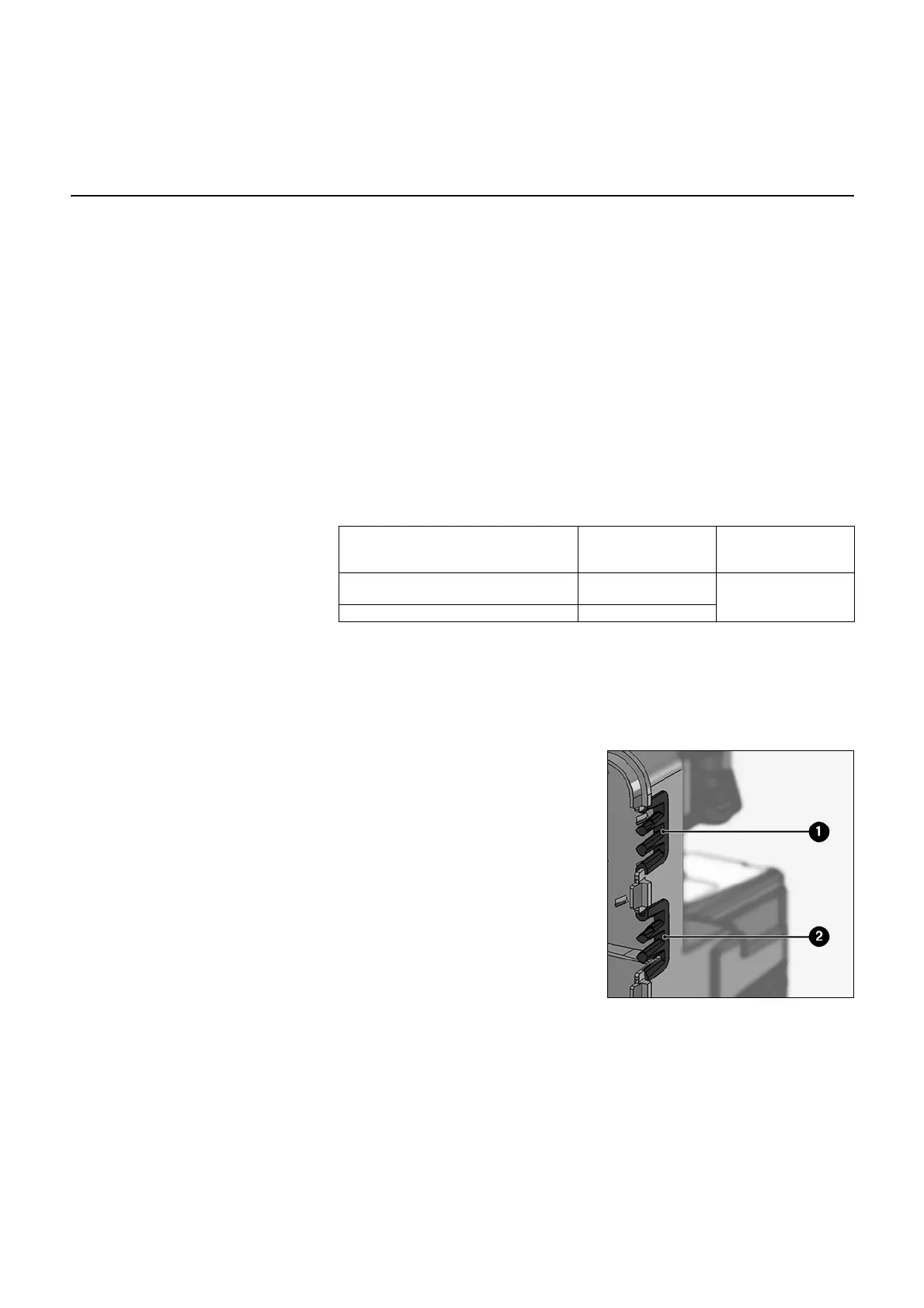
The connection cables for the burner
motor, the control voltage and the gas
train are fixed and routed through cable
grommets 1 and 2. They must be
connected to the terminal in accordance
with the electrical circuit diagram.
To this end, the following conductor
cross-sections must be observed:
Burner motor connection
The burner is supplied for a mains
supply voltage of 400V-50Hz, three-
phase current with a neutral wire and
earthing.
• Check the direction of rotation of the
fan motor via manual activation of the
burner protection device.
Connect the gas train using the
connectors supplied with the burner
(black to black, grey to grey).
Minimum
cross-section
[mm²]
Maximum
cross-section
[mm²]
Single-phase power supply
(control voltage)
1.5
4
Three-phase power supply (fan motor) 2.5
 Loading...