06/2016 - Art. Nr. 4200 1041 1103A 15
ACS150 manual control panel
Overview
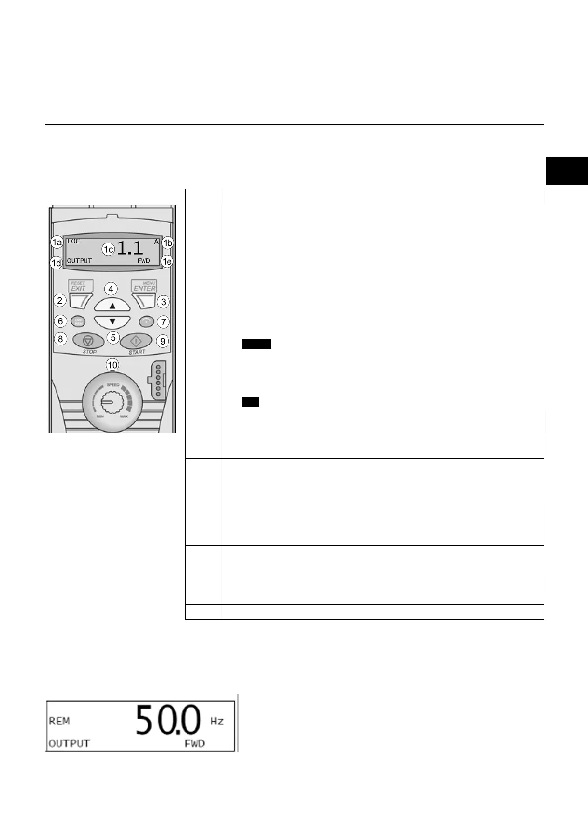
The following table summarises the key functions and displays of the basic control panel.
Current setpoint display by the Burnertronic
The general menu screen shows the currently activated motor frequency
Art. Use/Function
1 LCD display - Divided into five areas:
a. Upper left corner – control mode:
LOC: drive in local control mode (with micro-console)
REM: drive in remote control mode via E/A.
b. Top right corner – displayed value unit: Partial parameters mode for scrolling
the shortened parameters list.
c. Centre – variable content, generally displays parameter and signal values,
menus, or lists. Also displays malfunction and alarm codes.
d. Lower left corner and central area – micro-console operating mode:
OUTPUT: Display mode
PAR:
Continuously lit: Parameters mode
Flashing: Modified Parameters mode
MENU: Main menu
: Malfunction mode
e. Lower right corner – indicators:
FWD (forward)/REV (reverse): motor rotation direction
Slow flashing: stopped
Quick flashing: working, reference not reached
Lit: working, reference reached
: the value can be adjusted (in Reference or Parameters mode).
2 RESET/EXIT – accesses the next menu function without confirming a set value.
Reset to defaults in Output (display) and Fault (malfunction) modes.
3 MENU/ENTER – accesses the menu functions. Validation function for a value
set in Parameters mode.
4 UP arrow:
• Scrolls up in a menu or list
• Increases selected parameter value
Holding the button down causes the values to scroll more quickly.
5 DOWN arrow:
• Scrolls down in a menu or list
• Decreases selected parameter value
Holding the button down causes the values to scroll more quickly.
6 LOC/REM – switches between local and remote control
7 DIR – reverses motor rotation direction
8 STOP – stops drive in local control
9 START – starts drive in local control
10 Potentiometer – modifies reference frequency
Function
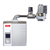
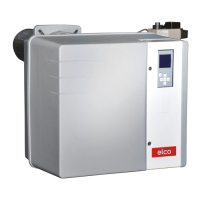
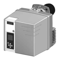
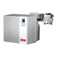
VGx MV/TC burner
Air regulation
ACS150 speed controller
 Loading...