06/2016 - Art. Nr. 4200 1041 1103A30
Commissioning
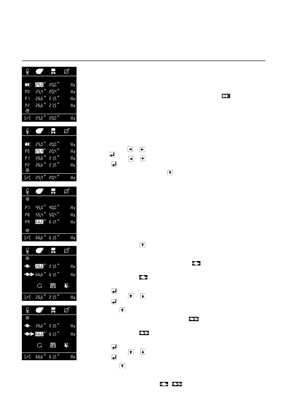
Menu 1: setting the servomotors
Setting with flame
Setting the ignition position
If a flame has been detected, the control and safety unit sets the burner to the ignition position as
soon as it receives the regulation authorisation.
- Set the fuel controller position and the air flap position according to the desired output level.
While doing so, constantly check the combustion values (CO, CO
2
O
2
, soot, NOx). If required,
adapt the gas (or fuel oil) pressure at the valve (or fuel-oil pump).
- Modify the position of the servomotors in the ignition position (lines with symbol). Proceed
as described on page 27, in the paragraph "Modifying the value of a servomotor position
setting".
- Warning: when modifying the value, the servomotor will move in real time. As a consequence,
the combustion values must be constantly checked.
The burner remains in ignition load.
Setting points P0-P9.
• Check the gas and/or fuel oil pressure. In the event of subsequent modifications, all setting
values must be corrected. For this reason, fine setting of the burner from point P9 must be
carried out, if necessary. At each setting point, check the combustion values and if necessary,
change the fuel controller position or the air flap position. To do so:
• Select air or fuel with or .
• Activate via (the cursor flashes).
• Change the value via or .
• Confirm with .
The next setting point is accessed using the key.
Note:
The values for each setting point are not saved until the next setting point is accessed. Each point
must be defined. It is not possible to skip individual points, as opposed to when setting without
flame. Only when all points (P0...P9) have been defined can the limit values for minimum and
maximum be set.
Further procedure:
• Enter the setting values in the log.
• Refine all setting points individually.
• Check the burner output at the maximum setting and raise or lower the fuel and air values if
necessary.
• Once all setting points P0 to P9 have been optimised, confirm them by navigating to the next
screen. To do so, press the key at point 9.
Note: The next screen can only be activated once all points (P0...P9) have been defined.
• The burner moves to the lower operating point, symbol (minimum regulation).
• Check the exhaust gas temperature, emissions and output at low load, if required, adapt the
burner output by correcting .
- To change:
• Activate with (the cursor flashes).
• Change the value via or .
• Confirm with .
Continue with the key
The burner moves to the upper operating point, symbol (maximum regulation).
• Check the exhaust gas temperature, emissions and output at low load, if required, adapt the
burner output by correcting .
- To change:
• Activate with (the cursor flashes).
• Change the value via or .
• Confirm with .
•
Continue with the key
The setting procedure is completed at this point, the burner switches to operating mode.
The burner switches to the lower operating point and waits for a heating request. The burner
operates within the preset output range ( - ) according to the settings of the control
thermostat.
 Loading...