Use and maintenance manual
Page 41
Engineering Department PHONE: +39 0532 829 965 - FAX: +39 0532 829 177
E-Mail: support@elenos.com
4. GENERAL DESCRIPTION
1
1
1
2
4.1.
Introduction
This technical manual contains information regarding the operation, use and
maintenance of the ETG250 (ETG300) exciter.
The ETG250 (ETG300) operates in the frequency band from 87.5MHz to
108MHz in steps of 10KHz and is capable of developing a maximum, continuous power
of 250W (300W).
All the operating controls of the unit are directly accessible from the front panel whilst all
the connectors are available on the rear panel.
The connectors for measurement of signals are however located on the front panel.
The exciter can be used for monophonic, stereo and composite multiplex transmissions.
The ETG250 (ETG300) exciter is available in two versions which are identical
from an operational point of view but have different power supply circuitry.
4.2.
Using the
block diagram
The block diagrams describing the two versions of the ETG250 (ETG300) exciter
are on the following two pages.
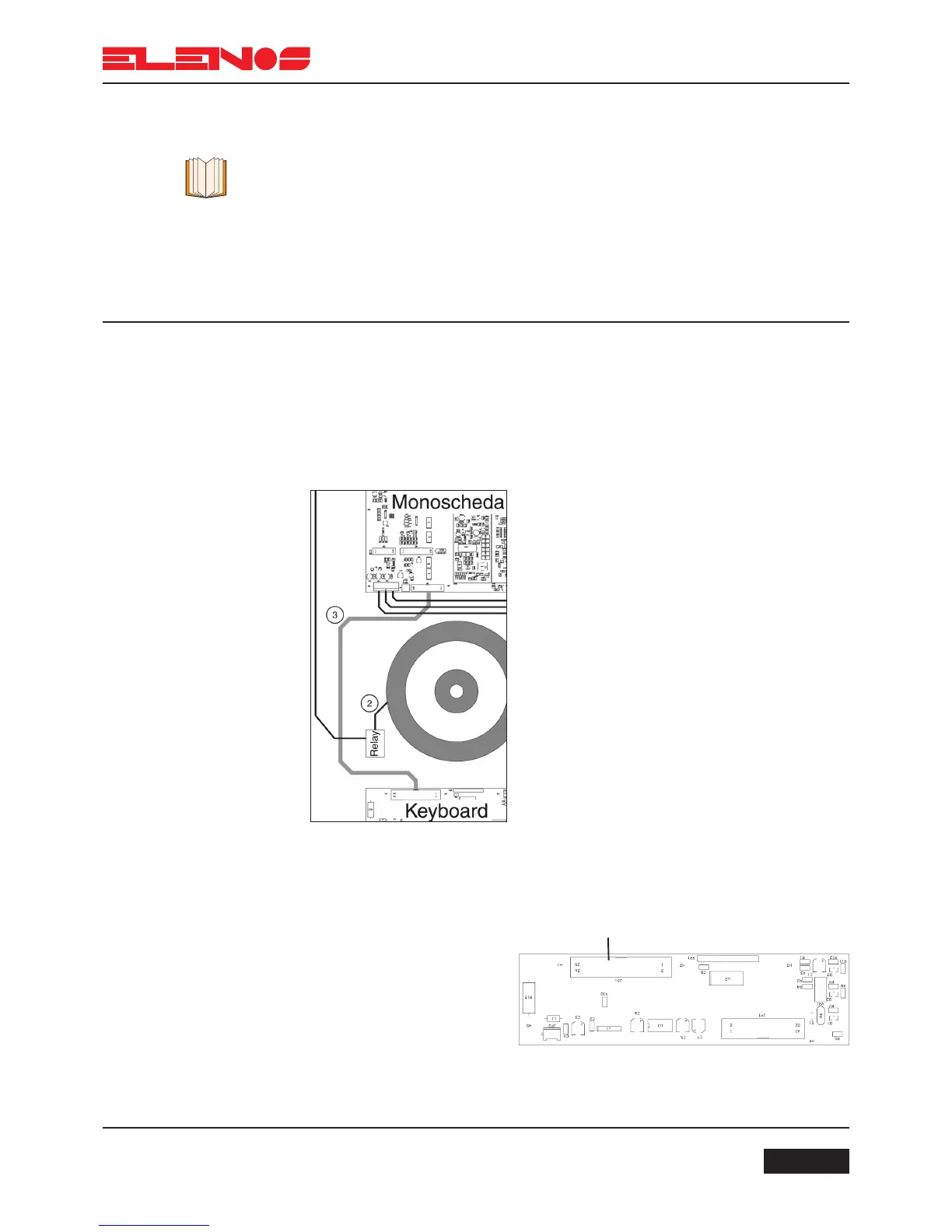
The principle of communication between the various boards is clear from their
interconnection; each connection is identified by a progressive number within a circle. In
the pages following the block diagram where individual boards are decribed, the cable
loom numbers are identified in order to simplify maintenance and eventual repair.
In this case, for example, the board is connected to
the keyboard via flat 3, and the transformer is con-
nected to the relay via cable 2 etc.
In the board descriptions following the block dia-
gram, the following information appears:
Connections:
- 1 (JD1) via cable flat 3 to 1 (J1) of the monoboard
The first number is a reference whilst the number in
brackets represents the name of the connector of the
board in question.
For more detail, see the layouts of the schematics.