Use and maintenance manual
Page 50
Engineering Department PHONE: +39 0532 829 965 - FAX: +39 0532 829 177
E-Mail: support@elenos.com
4. GENERAL DESCRIPTION
1 2 3
4
5
1
2 3
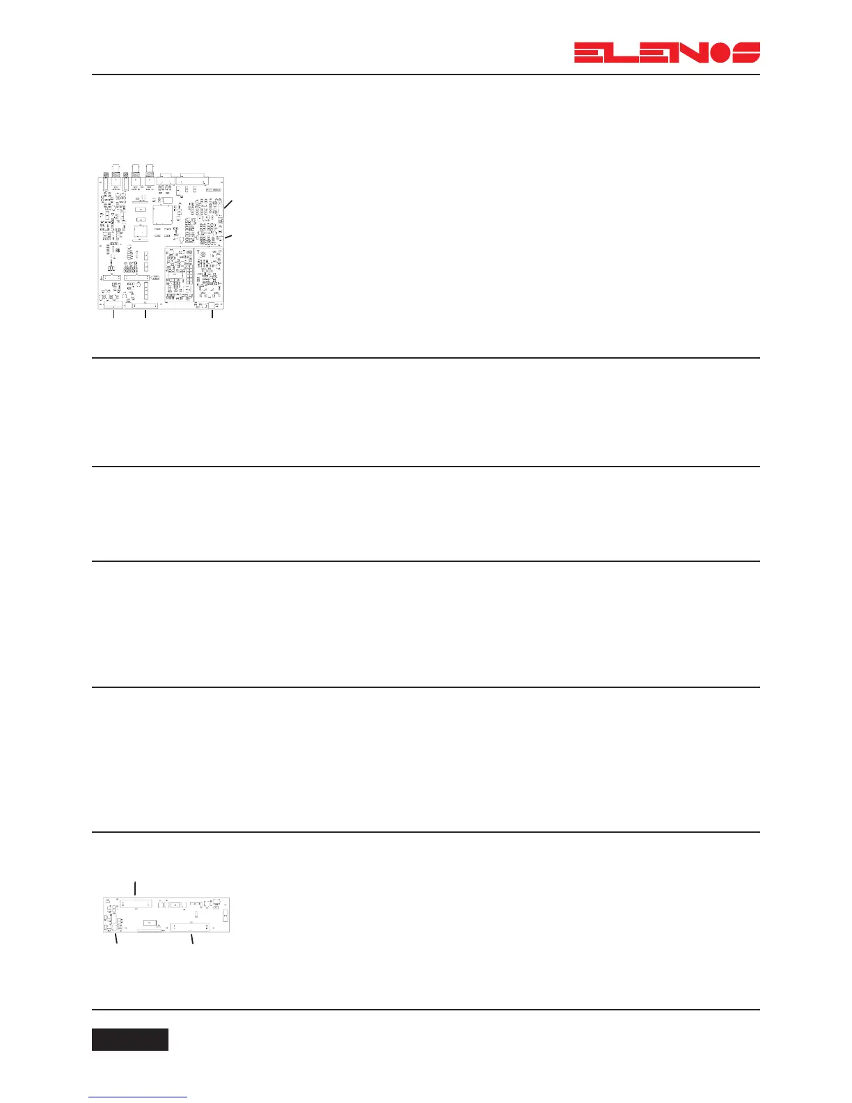
4.6.
Logic
(Mother board)
This board is constructed using only SMD technology and comprises the fol-
lowing stages:
- CPU
- AGC
- VCO/PLL
- MPX
Connections:
- 1 (J1) via cable 4 to 2 (CN2) of the services (auxiliary) power supply
- 1 (J1) via cable 5 to 1 of the power supply (dependant on the version)
- 1 (J1) via cable 6 to 2 of the RF Modules
- 2 (JD1) via cable flat to 1 (JD1) of the Keyboard
- 3 (SC1) via coaxial cable 10 to 1 of the Driver
- 4 (CN2) via cable 12 to the temperature sensor
- 5 (CN1) via cable flat 11 to 1 of the directional coupler
4.6.1.
CPU
The CPU controls the display, the keyboard, ALC and the VCO/PLL. It comprises
an 80C552 microprocessor which operates at a clock rate of 16MHz.
It features a 256 Kbit RAM and a 2Mbit ROM.
It receives input signals from the directional coupler and supplies processed
signals to the ALC.
It also controls all the audio functions.
4.6.2.
ALC
This receives signals from the CPU and supplies 2 output voltages:
1) Controls the MOS gates
2) Controls the output voltage of the power supply.
It features SWR protection which limits the output power in the event of an SWR
in excess of the programmed threshold.
4.6.3.
VCO/PLL
The PLL board generates the frequency-modulated RF signal using phase-lock
synthesis.
The oscillator, controlled by the VCO voltage and mounted next to the PLL board,
uses very low-noise components and also separation stages to obtain very low phase
noise.
The reference frequency is generated by a temperature-compensated oscillator
with a maximum drift of 1ppm.
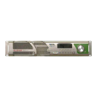
4.7.
Keyboard
This is interfaced to the CPU and supplies signals to the display as well as power
for illumination.
A trimmer allows adjustment of the contrast.
8 soft keys perform functions shown on the display.
Connections:
- 1 (JP1) via flat cable 3 to 2 (JD1) of the mother board
- 2 via cable 8 to the display
- 3 (JD1) via flat cable 9 to the display
4.6.4.
MPX
Accepts the wide-band MPX input signal, i.e. it supplies the transmitter with a
stereo signal derived from an external stereo encoder. It features 2 SCA inputs, one of
which can be used as an RDS data input.
The two unbalanced inputs for SCA signals accept input frequencies upto 200
KHz. The MPX also supplies the microcontroller with an appropriately processed MPX
signal so that the level can be displayed as a bar graph and in dBV values. The inputs are
protected against over-voltage.
The inputs are unbalanced on BNC connectors (impedance 10KOhm).