2
3
1
4.4.
Power supply section
The ETG250 (ETG300) uses a switch-mode converter in the transformer version
and a switch-mode power supply connected direct to the line supply in the other version
(DR).
The section which supplies power to the services is the same for both versions.
The ETG250 (ETG300) exciter features, on both versions, a line filter fitted to the alterna-
ting supply to provide maximum suppression of conducted interference.
The use of discrete component technology enables easy replacement in the event of fai-
lure.
4.4.1.
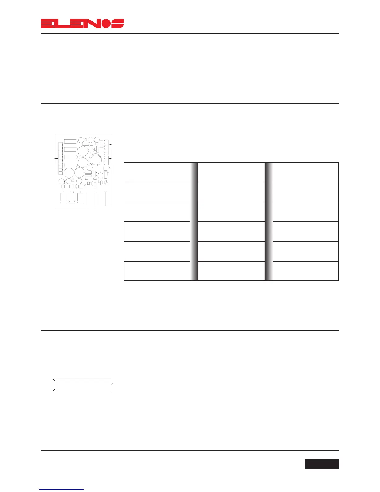
Service power supply
The service (or auxiliary) power supply furnishes 5 separate supplies which supply
the various boards which go to make up the unit.
The table below summarises the supply voltages for each section of the unit and
the corresponding protection.
The service (or auxiliary) power supply is a linear type in order to reduce to a
minimum any disturbances that could interfere with the boards.
Connections:
- 1 (CN1) via cable 13 to 2 to the “DRIVER” board
- 2 (CN2) via cable 4 to 1 (J1) of the mother board
- 3 (CN3) via cable 7 to the transformer
4.4.2.
Switch-mode power
supply (DR version)
Supplies a variable voltage from +30V to +50V, with current and voltage protection.
It uses a mix of SMD and traditional technology to reduce the space occupied as far as
possible.
The power supply features thermal protection and a further line filter equipped with VDRs
on the input.
Connections:
(only in the switch-mode DR version)
- 1 via cable 2 to the relay
- 2 via cable 5 to 1 (J1) of the mother board
- 3 via cable 18 to 3 of the RF modules
Supply Voltage
+12V
-12V
+5V
+12V
RF
+18V
RF
Boards supplied
Mother board
(CPU, PLL, BUS)
Mother board
(CPU, PLL, BUS)
Mother board
(CPU, PLL, BUS)
RF driver stage
RF driver stage
Protection
Current protection
Current protection
Current and voltage pro-
tection
Current protection
Current protection