1
2
3
4.4.2.2.
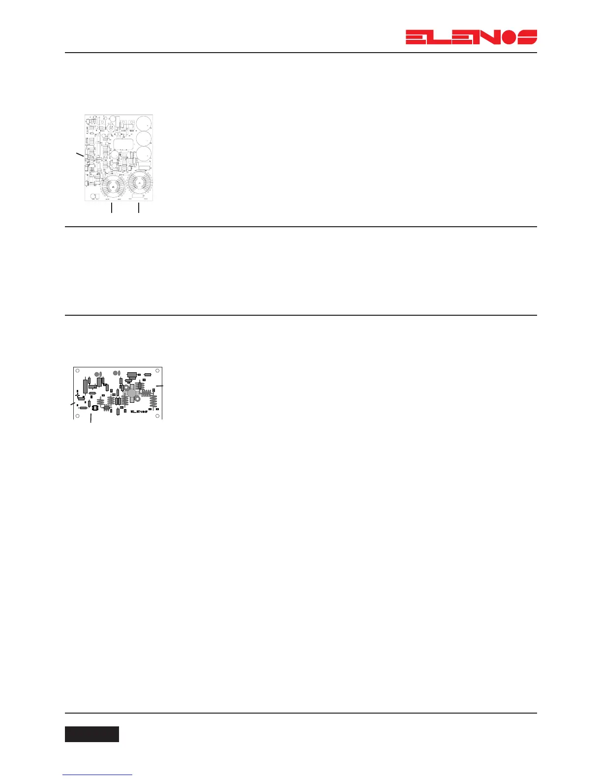
Transformer power
supply
Supplies a variable voltage from +20V to +50V with voltage and current protection.
Uses traditional technology to facilitate replacement of faulty parts.
The power supply also features thermal protection and both input and output filters in
order to minimise interference.
Connections:
(Only for the transformer version)
- 1 via cable 5 to 1 (J1) of the mother board
- 2 via cable 18 to 3 of the RF modules
- 3 via cable 19 to 1 (J1) of the mother board
4.5.
Radiofrequency
section
The driver comprises an input stage of about 10mW and supplies a maximum
output power of 15W.
It is built using a mix of technologies and subdivided into three main amplifying
stages.
The first stage is a “MMIC” type “ERA5”.
The second stage is a MOS BLF404.
The third stage is a MOS BLF244.
The output of the driver is connected to the input splitter.
Connections:
- 1 via coaxial cable 10 to 3 (J8 RF OUT) of the mother board
- 2 via cable 13 to 1 (CN1) of the services power supply (auxiliary)
- 3 via coaxial cable 14 to 1 of the input splitter (Splitter IN)
4.5.1.
Driver
This comprises a low power output stage (driver) which, via a splitter, supplies the
power to the two final power stages.
The power output from the modules supplies a coupler (or output adder) which
concentrates all the power to the input of the low-pass filter.
The measurement probe which is located on the final part of the low-pass filter,
reads the values of direct and reflected power for the CPU.