1
2
3
1
1
2
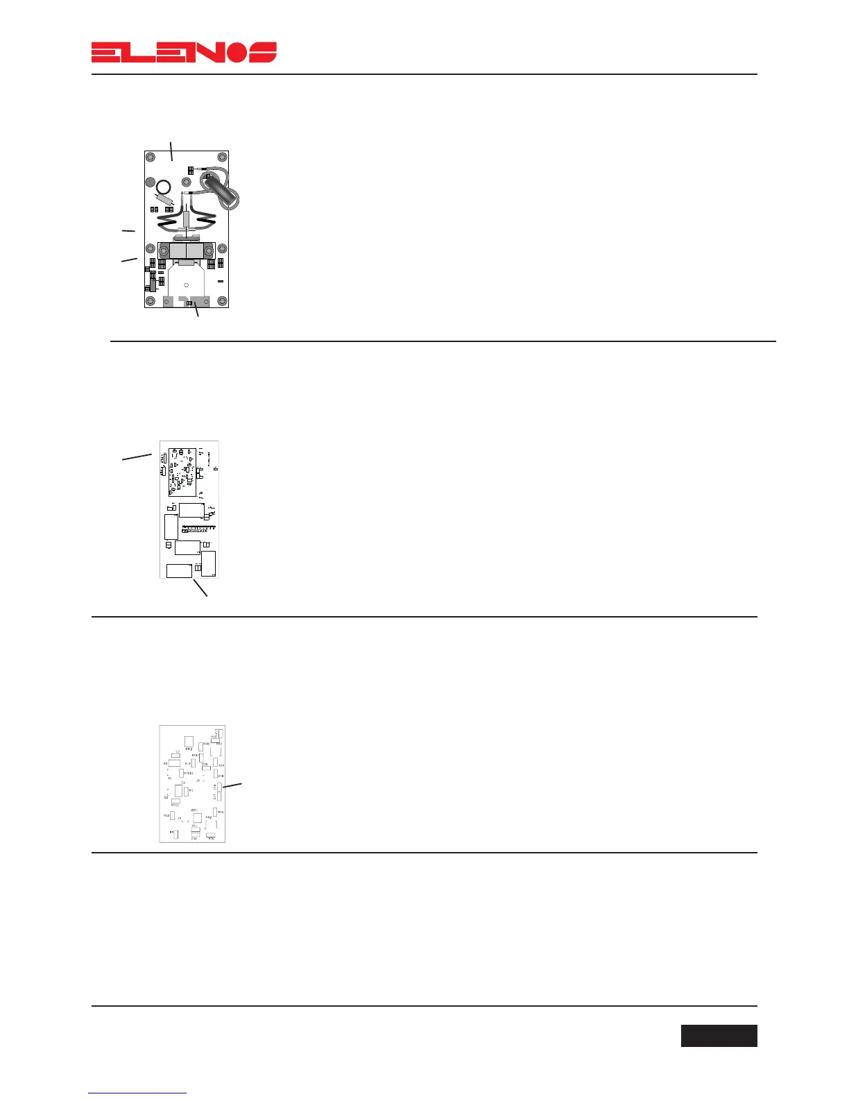
RF Out
4.5.2.
RF Modules
The two modules comprise a MOSFET (BLF278) and are capable of delivering a
maximum power of 300W each.
The gates are controlled by the CPU so that power output can be inhibited when
the user changes frequency.
The outputs of both modules enter the couple (or output combiner).
Connections:
- 1 via coaxial cables 15 and 16 to 2 and 3 of the input splitter (Splitter IN)
- 2 via cable 6 to 1 (J1) of the mother board
- 3 via cable 18 to 2 of the power supply (this is dependant on the version of power
supply)
- 4 via coaxial cable 17 to 2 of the low-pass filter (LPF INPUT)
4.5.3.
Low-pass filter
This is a ninth order “CHEBYCHEV” filter, with teflon support. It guarantees the
suppression of harmonic components with the limits set by International standards.
Connections:
- 1 (JP1) via flat cable to 5 (CN1) of the mother board
- 2 via coaxial cable 17 to 4 of the RF Modules
“RF Out” indicates the RF power output connector which is located on the rear panel
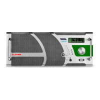
4.5.4.1.
Directional coupler
Output power
measurement
The directional coupler is located on the final output stage of the low-pass filter.
It is designed using SMD technology and is shielded to prevent RF intereference.
It generates a voltage proportional to the direct and reflected power.
Connections:
- 1 (JP1) via flat cable 11 to 5 (CN1) of the mother board
N.B.
The directional coupler is mounted on the same circuit board.
4.5.4.2.
Directional coupler
AGC protection
A control circuit regulates the output power and maintains it to within +0.1dB
across the whole operating band, progressively reducing it down to 50W in the event of
excessive SWR. This enables the exciter to continue to work with infinite SWR at any phase
angle.