Use and maintenance manual
Page 54
Engineering Department PHONE: +39 0532 829 965 - FAX: +39 0532 829 177
E-Mail: support@elenos.com
4. GENERAL DESCRIPTION
The system, selected by an international working group of specialists, allows data
transmission at a speed of 1187.5 bit/sec with phase modulation at two levels, 57KHz
carrier and band +/- 2KHz. The transmitted binary signal undergoes differential enco-
ding.
The transmission protocol comprises packets of 104 bit (87.6ms) length, named
GROUPS, each comprising 4 BLOCKS of 26 bits each. Each BLOCK is made up of 16
bits of information and 10 protection bits, designed specifically to allow words to be cor-
rected upto a maximum of 5 bit in error. 16 distinct GROUPS are provided, some of
which have not yet been defined. Each group starts with an identification code (PI) which
has the double scope of synchronising the receiver and identifying the broadcaster that is
transmitting the signal. The PI comprises a 4 bit code to identify the country (Italy is code
5), a 4 bit code to define the coverage of the transmitted signal (International, National,
Sub-National,Regional or Local) and an 8 bit code for the number of reference of the
program.
The Zero GROUP is used for sending the PS message (shown on the display of
RDS compatible receivers) and for tuning frequencies. Each Zero group contains 2 cha-
racters of the message, two tuning frequencies, a code which defines the type of transmis-
sion (mono, stereo, compressed, etc.), a bit to define whether music or speech is being
transmitted and a code for signalling the transmission of traffic news.
Two formats are provided for the transmission of alternative frequencies:
A) Each station transmits a unique list of frequencies, preceded by the number of frequen-
cies that it contains (max 25);
B) Each station transmits a unique list of frequencies for each transmitter that it possesses.
The list begins with the header frequency, followed by the frequencies (max 12) used by
adjacent transmitters in the coverage area. This method is more efficient when the list
of frequencies is long because it presents the self-tuning system with fewer frequencies
to choose from and thus speed up the process of searching for new frequencies. If the
number of frequencies is low, mode A is advised as it requires less data to be transmit-
ted.
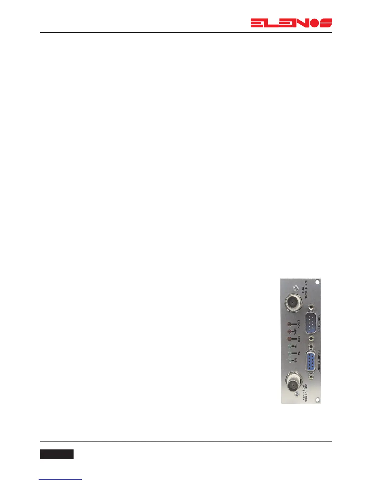
4.8.3.
RDS board
RDS system
The RDS encoder comprises a single Euro card offe-
ring the following features:
Connector 41612 which accepts the power supply volta-
ges +5V and +12V
BNC for the input of the mono or stereo signal
BNC for the ouptput of the MPX signal and/or MPX+RDS
Cannon connector 9 PIN for serial connection to a PC
Cannon connector 9 PIN for connection of a remote key-
board
A panel-mounted trimmer for adjusting the RDS signal
level
Led indicator, for lock and carrier generation RDS (LOCK)
Led indicator, for synchronisation with stereo carrier
(STEREO)
Led indicator for remote control active (REM)
Led indicator for TP set (TP)
Led indicator for TA set (TA)
Led indicator for MS set (MS