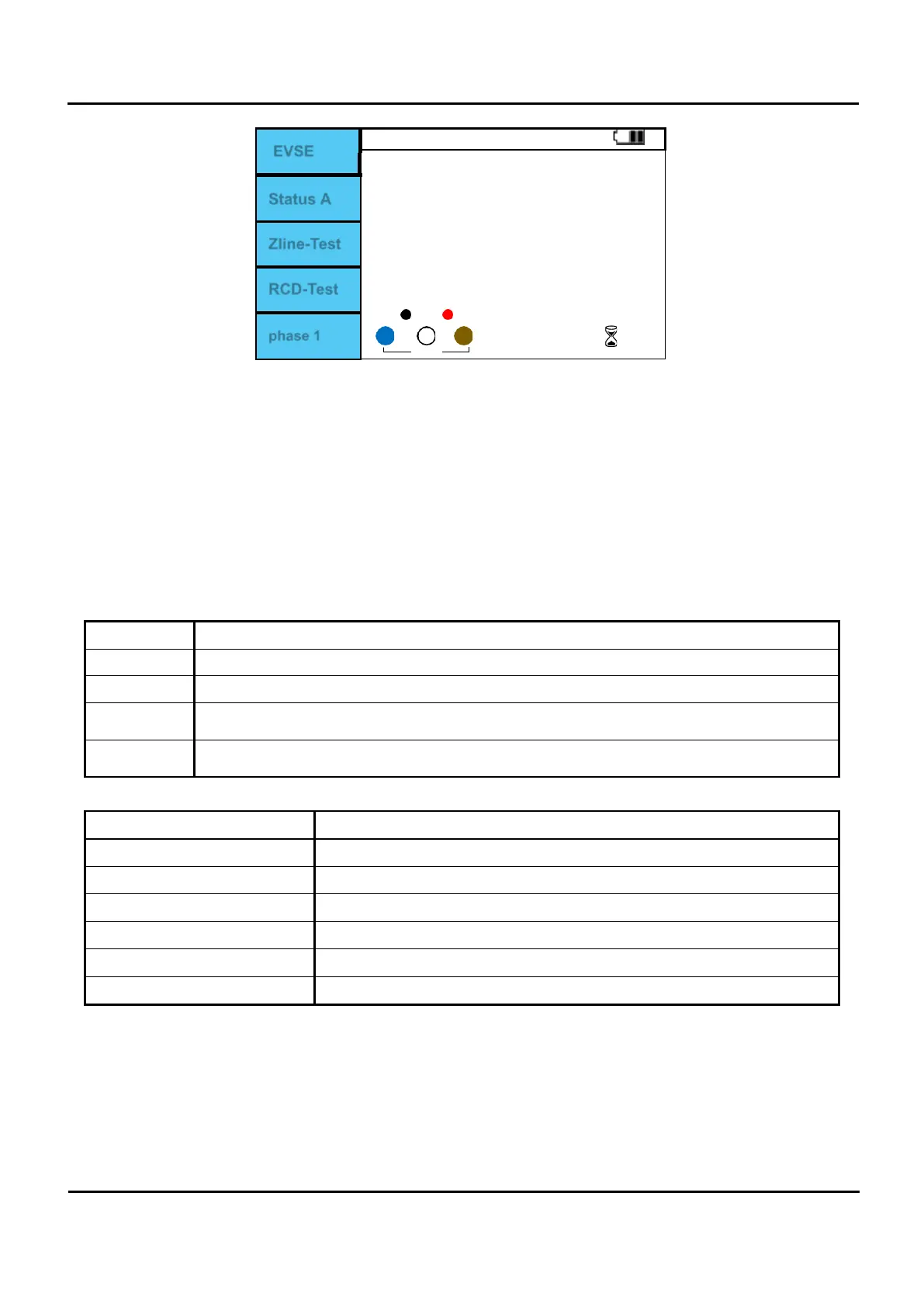
EVSE
Available charging current
---
A
Ipsc ---A / Zline ----- Ω
0 --- ms / 180 ---- ms
0
X X X
0
0
Status A
Zline-Test
RCD-Test
phase 1
Figure 6.10.10 Adaptor/ EVSE screen.
I.
Position the rotary switch on the Adaptor.
II.
Press F1 button to set EVSE.
III.
Check Figure 6.10.9 and Input terminal Table 6.10.1 and connect correctly.
IV.
Press the Test button to form Status A.
V.
There is only a relay sound and there is no change in the EuroMaster AutoEv screen.
VI.
Press F2 button to change to Status B, Status C, Status E.
VII.
In Status C, measure the duty of the pulse input at CP and display the available charging current.
VIII.
With Status C, voltage is output to L-N or L-L, and F3 (Zline-Test) and RCD-Test can be performed.
(When L-N and L-PE voltages are input, Zline and RCD can be measured using the F3 and F4 buttons.)
Status EVSE Status Output.
A
No connection to the vehicle.
B
Cable assembly vehicle and EVSE connected.
C
The maximum charging current is calculated and displayed by Duty output from EVSE, and
the power is connected.
E
Short between PE-CP and set the voltage to 0V. Create an Error state like this and confirm
that EVSE displays Error.
Table 6.10.2 EVSE Status.
Duty Cycle maximum charging current
≤
≤
Charging not allowed.
≤
≤10
6A
10%≤ Duty cycle ≤85%
allowable current = (% duty cycle) x 0.6A
85%≤ Duty cycle ≤96%
allowable current = (% duty cycle – 64) x 2.5A
≤
≤97
80A
Duty cycle > 97% Charging not allowed.
Table 6.10.3 Maximum charging current due to duty cycle.