L-L / Z-line
L1
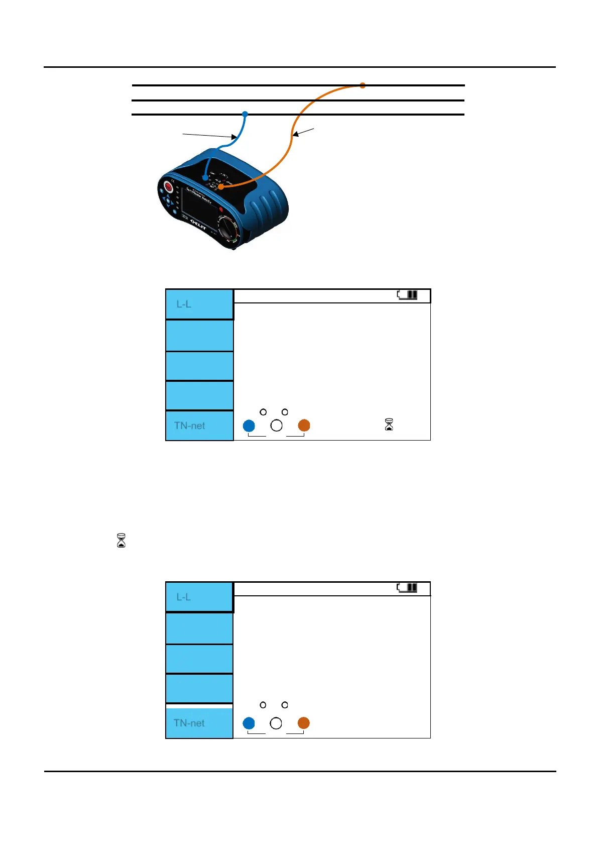
Figure 6.5.10 Z-line / L-L Connection.
L-L
Ips 0.76
----
R:
---- Ω
XL: ------- Ω
TN-net
Figure 6.5.11 Z-line / L-L screen.
I.
Set the rotary switch to Loop / Z-line.
II.
Press F1 button to change L-PE L-N L-L.
III.
Connect the test leads as shown in Figure 6.5.10.
IV.
If there is no problem with the test lead connection, “OK” is displayed as shown in Figure 6.5.11.
V.
When “OK” is displayed, press the Test button to perform measurement.
VI.
The symbol is displayed during measurement.
VII.
VII. When the measurement is completed, the L-L impedance measurement value and PSC value are
displayed on the screen.
L-L
Ips 0.76
R:
0.65 Ω
XL: 0.03 Ω
TN-net
Figure 6.5.12 Z-line / L-L Measurement completed.