L-N
10A
B
Ips 0.76
----
R:
---- Ω
XL: ------ Ω
TN-net
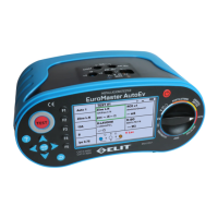
Figure 6.5.8 Z-line / L-N screen.
I.
Set the rotary switch to Loop / Z-line.
II.
Press F1 button to change L-PE to L-N. Function Name is changed to ZLINE.
III.
Connect the test leads as shown in Figure 6.5.7.
IV.
If there is no problem with the test lead connection, the terminal status is displayed as shown in Fig.
6.5.8 "OK" is displayed in the right window.
V.
When “OK” is displayed, press the Test button to perform measurement.
VI.
The symbol is displayed during measurement.
VII.
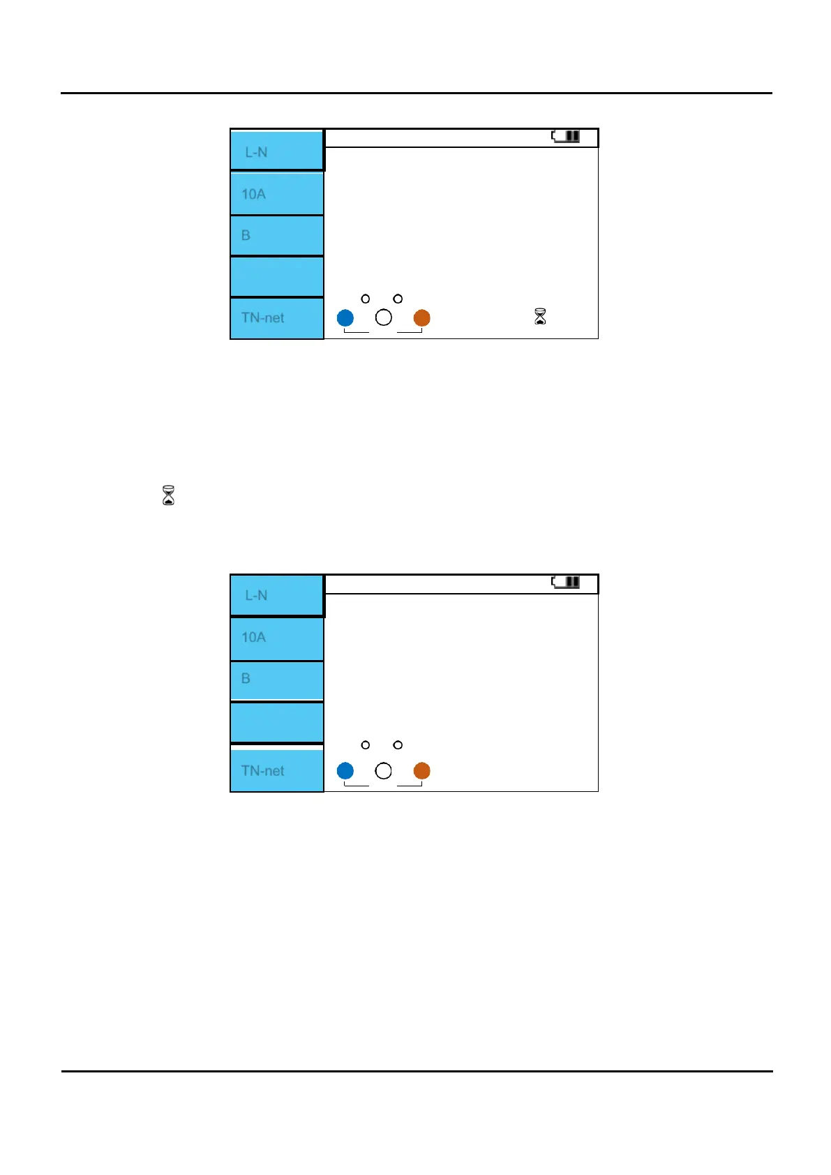
When the measurement is completed, the L-N impedance measurement value and PSC value are
displayed on the screen.
L-N
10A
B
Ips 0.76
268 A
R:
0.65 Ω
XL: 0.04 Ω
TN-net
115 115
Figure 6.5.9 Z-line / L-N Measurement completed.
Set Fuse rating with F2 button. (10A, 13A, 16A, 20A, 25A, 32A)
Set Fuse type with F3 button. (B, C, D, gG, gL)
The F4 menu window is displayed with a value of PCS (Ips) x 0.76.