I.
Set the rotary switch to Loop / Z-line.
II.
Press the F2 button to change from No Trip to Hi Amp.
III.
Connect the test leads as shown in Figure 6.5.4.
IV.
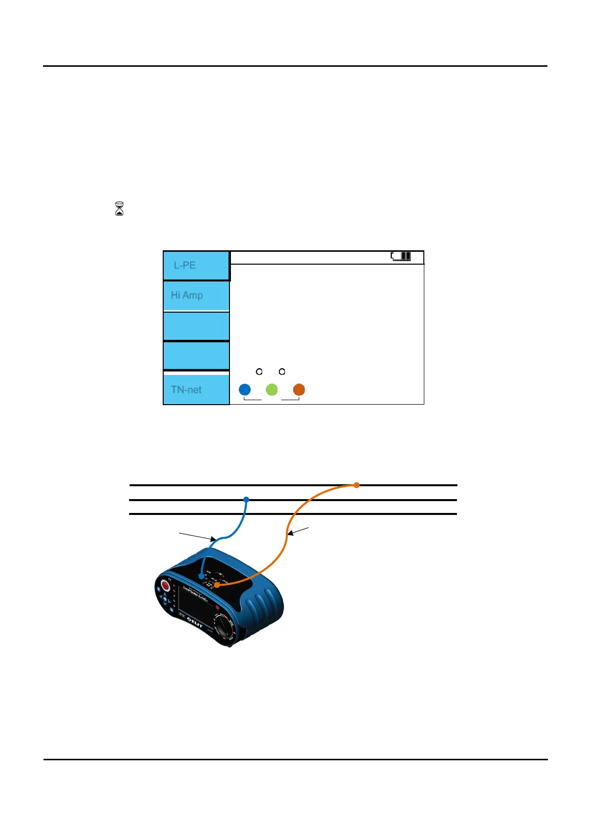
IV. If there is no problem with the test lead connection, the terminal status is displayed as shown in
Figure 6.5.5 “OK” is displayed in the right window.
X X X : This display indicates that there is no L, PE, or N connection.
L↔N : This is an indication that the L and N lines have been switched.
L↔PE : This is an indication that the L and PE lines have been switched.
N X : This indicates that there is no N-line connection.
PE X : This indicates that there is no PE-line connection.
V.
When “OK” is displayed, press the Test button to perform measurement.
VI.
The symbol is displayed during measurement.
VII.
When the measurement is completed, the L-PE impedance measurement value and PFC (If) value
are displayed on the screen.
L-PE
Hi Amp
R: 0.65 Ω
XL: 0.05 Ω
0
OK
TN-net
0 230
Figure 6.5.6 Loop / Hi Amp Measurement completed.
Do not measure where RCD is installed. RCD is tripped.
Z-Line / L-N
N(Blue)
L
N
PE
L (Brown)
Figure 6.5.7 Z-Line / L-N Connection.