I.
Set the rotary switch to RCD.
II.
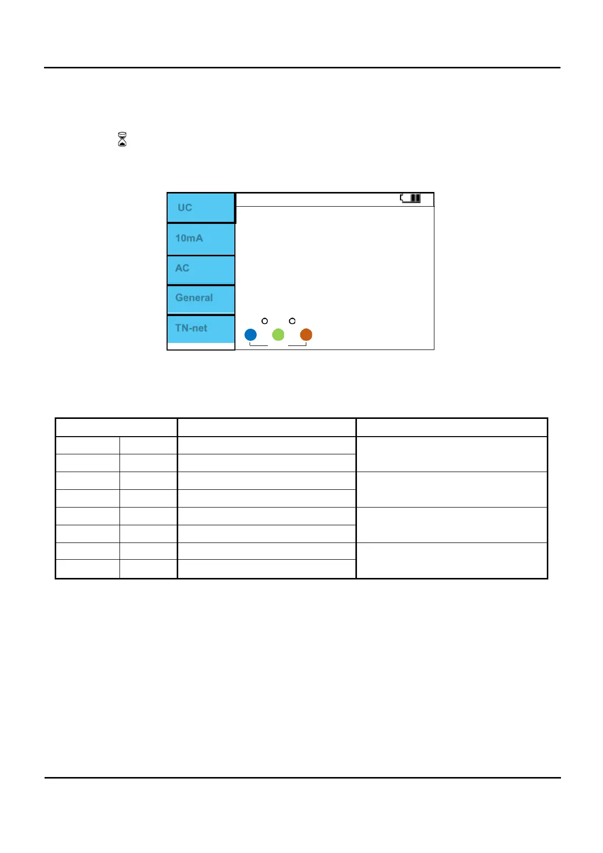
Press F1 button to change to Uc.
III.
Connect the test leads as shown in Figure 6.6.1.
IV.
If there is no problem with the test lead connection, “OK” is displayed as shown in Figure 6.6.4.
V.
When “OK” is displayed, press the Test button to perform measurement.
VI.
The symbol being measured is displayed.
VII.
When the measurement is complete, the RCD Contact voltage and Ri values are displayed on the
screen.
UC
10mA
AC
General
0
OK
TN-net
1 230
Figure 6.6.5 RCD / Uc Measurement completed.
Calculated as Ri = Uc / I∆n
RCD type Contact voltage Uc Rated I∆n
AC General 1.05 x I∆n
any
AC Selective 1.05 x I∆n x 2
A,A+6mA General 1.05 x I∆n x 1.4
≥ 30mA
A,A+6mA Selective 1.05 x I∆n x 1.4 x 2
A,A+6mA General 1.05 x I∆n x 2
< 30mA
A,A+6mA Selective 1.05 x I∆n x 2 x 2
B
General 1.05 x I∆n x 2
any
B
Selective 1.05 x I∆n x 2 x 2