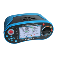
RCD / x1/2, x1, x2, x5 (Trip-time)
1x
10mA
AC
General
Uc: --------- V
Ri: --------- Ω
0
1
230
OK
TN-net
Figure 6.6.8 RCD / x1/2,x1,x2,x5 screen.
I.
Set the rotary switch to RCD.
II.
Press F1 button to change to x1/2, x1, x2, x5.
III.
Connect the test leads as shown in Figure 6.6.1.
IV.
If there is no problem with the test lead connection, “OK” is displayed as shown in Figure 6.6.8
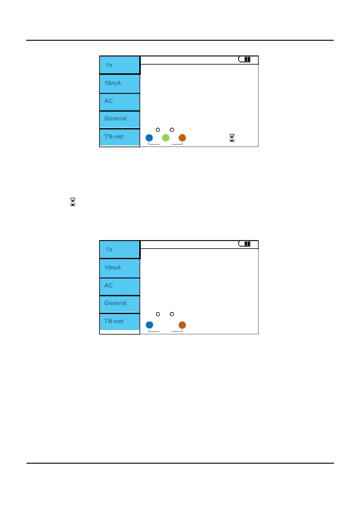
V.
When “OK” is displayed, press the Test button to perform measurement.
VI.
The symbol being measured is displayed.
VII.
The voltage phase 0 ° is measured first and the Trip time is displayed.
VIII.
When the 0 ° measurement is completed, turn on the RCD switch and measure 180 °.
IX.
When all measurements are completed, the RCD 0 ° and 180 ° Trip time will be displayed on the
screen.
1x
10mA
AC
General
Uc: 10.5 V
Ri: 1000 Ω
0
OK
TN-net
1 230
Figure 6.6.9 RCD / x1/2,x1,x2,x5 Measurement completed.