Optional Remote Control EEC-0039 V1.1
Remote Control (Optional)
point with boom length, angle and load radius information along with allowable load and
actual load values.
Powering up the transmitter
To start using the remote controls, this sequence must be followed to power up the
transmitter for use. These procedures are also located on a decal on the bottom
side of the transmitter.
1. Ensure all switches and joysticks are in the neutral position. Any two position
toggle switches need to be in the lower position. (Transmitter will not power up if
the switches are not in neutral position).
2. Select and release the Power switch in the “ON/Horn” direction.
The Red, Emergency Stop light will flash quickly.
3. Release the Emergency Stop (Red button on side of transmitter) by rotating
clockwise. The yellow (Active) light on the transmitter will begin to flash
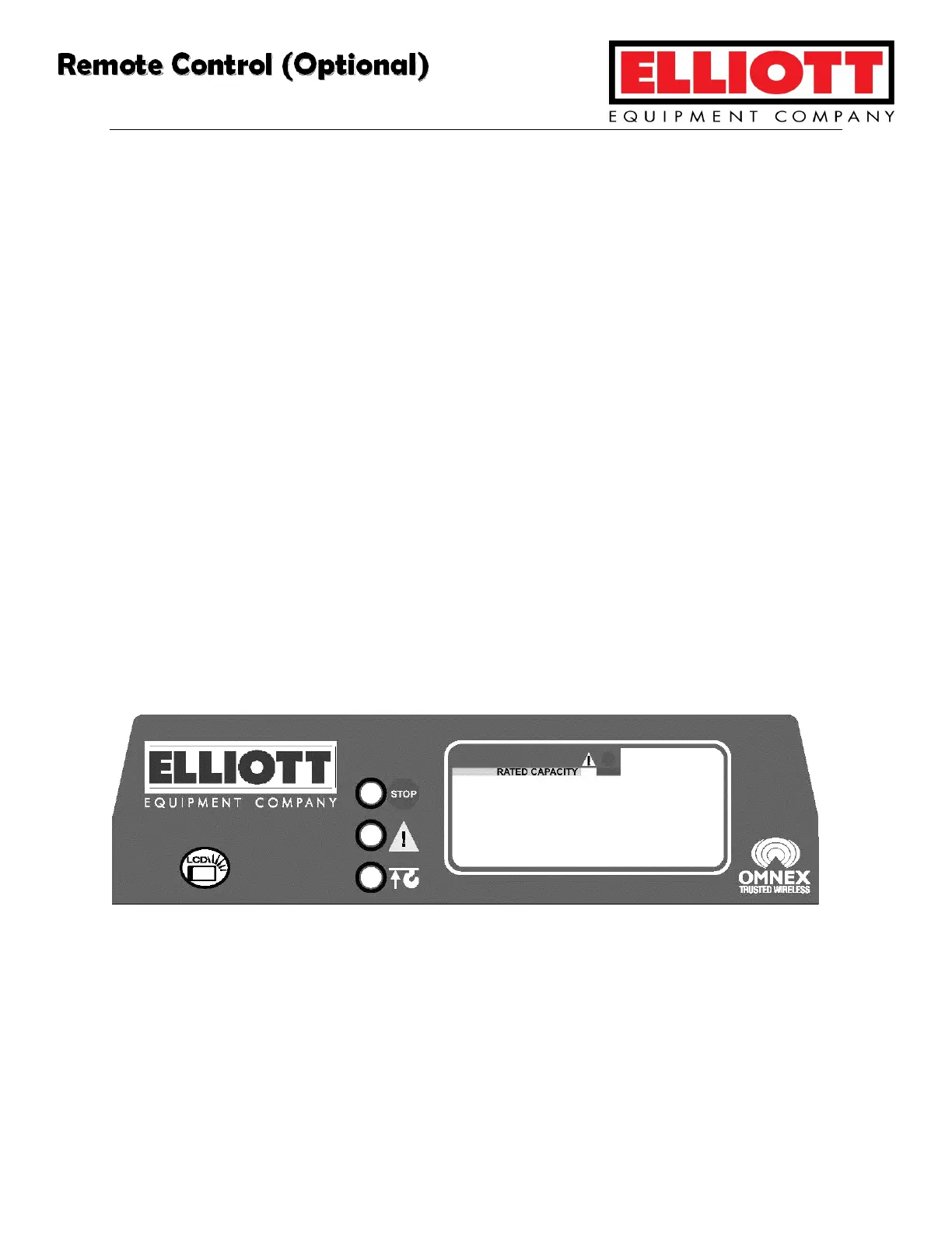
Indicator Panel
Indicator Panel lights are, from top to bottom: E-Stop, Active, and Battery/Pendant. For
complete information on interpreting these lights, see the Component Service section
of this manual.
Complete Remote Control System Manufactures Manual is included with this manual in
the Component Service section. Refer to this section for complete troubleshooting,
calibration, and communication information.
 Loading...