The impedance of the wire must be as low as possible. The size of the wire must be
thicker than actually required by the carrying current. 24 or 26 AWG wire for control
and feedback cables is satisfactory.
Use shielded wires for motor connections as well. If the wires are long, ensure that the
capacitance between the wires is not too high: C < 30 nF is satisfactory for most
applications.
Keep all wires and cables as short as possible.
Keep the motor wires as far away as possible from the feedback, control and
communication cables.
Ensure that in normal operating conditions, the shielded wires and drain carry no
current. The only time these conductors carry current is under abnormal conditions,
when electrical equipment has become a potential shock or fire hazard while
conducting external EMI interferences directly to ground, in order to prevent them
from affecting the drive. Failing to meet this requirement can result in
drive/controller/host failure.
After completing the wiring, carefully inspect all wires to ensure that the crimp
terminals are firmly attached to the wire ends and that the wires are firmly connected
to their connectors.
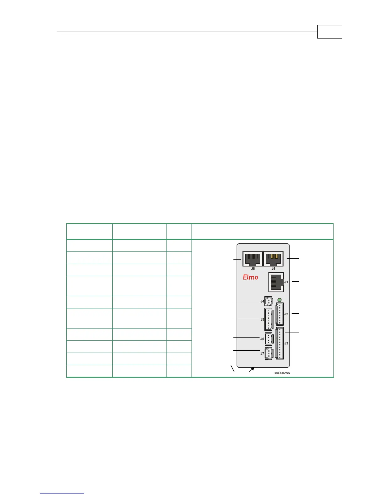
The following connectors are used for wiring the Bassoon.
Type Function Port Connector Location
8-pin RJ-45 CANopen J8
8-pin RJ-45 CANopen J9
8-pin RJ-45 RS-232 J1
8-pin Molex Auxiliary
Feedback
J2
12-pin Molex Main Feedback J3
2-pin Molex Auxiliary power
supply
J4
8-pin Molex Digital input J5
4-pin Molex Digital output J6
3-pin Molex Analog input J7
7-pin Phoenix Main power Power