Index
A
Advanced position control · 2-2
Ambient operating temperature · 3-1
Analog input
Cable · 3-30
Specifications · A-16
Auxiliary
Feedback cable · 3-20
Power cable · 3-10
Power supply · 2-1
B
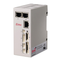
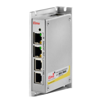
Bassoon
Connection diagram · 3-7
Connectors · 3-6
Dimensions · A-3
Initializing · 3-34
Installation · 3-1
Mounting
Directly on wall · 3-5
On DIN rail · 3-4
Powering up · 3-34
Technical specifications · A-1
Type designation number · 3-3
Unpacking · 3-3
Wiring · 3-5
C
Cables
Auxiliary feedback · 3-20
Auxiliary power · 3-10
Communication · 3-31
I/O · 3-27
Main Power · 3-9
Motor · 3-8
CANopen · 3-31, 3-32
Communication · 2-2
Communication cables · 3-31
Compliance standards · 1-3, A-19
Composer · 2-1, 3-34
Conformance · 1-3, A-19
Connecting
Auxiliary power cable · 3-10
Main power cable · 3-9
Motor cables · 3-8
Power cables · 3-8
Connection diagram · 3-7
Control connector · A-5
Control specifications · A-7, A-8
Current control · 2-1
D
Differential auxiliary input · 3-22, 3-25
Differential pulse-and-direction input ·
3-26
Digital input
Cable · 3-27
Digital output
Cable · 3-29
Digital output interface · A-14
Dimensions · A-3
DIN rail mounting · 3-4
E
Environmental conditions · A-4
F
Fault protection · 2-3
Feedback
Connector · A-5
Options · 2-2, A-8
Supply voltage · A-9
Feedback options · A-9, A-10, A-11, A-
12, A-13
Feedbacks
Potentiometer · A-12
Tachometer · A-11
G
Grounding · 1-1
Analog input cables · 3-30
Auxiliary power cable · 3-10
Bassoon Installation Guide
MAN-BASIG (Ver 1.4)
I-1