3.5.4 Feedback and Control Cable Assemblies
The Auxiliary Power Cable (J4), the Feedback cables (J2 and J3) and the I/O cables (J5, J6 and
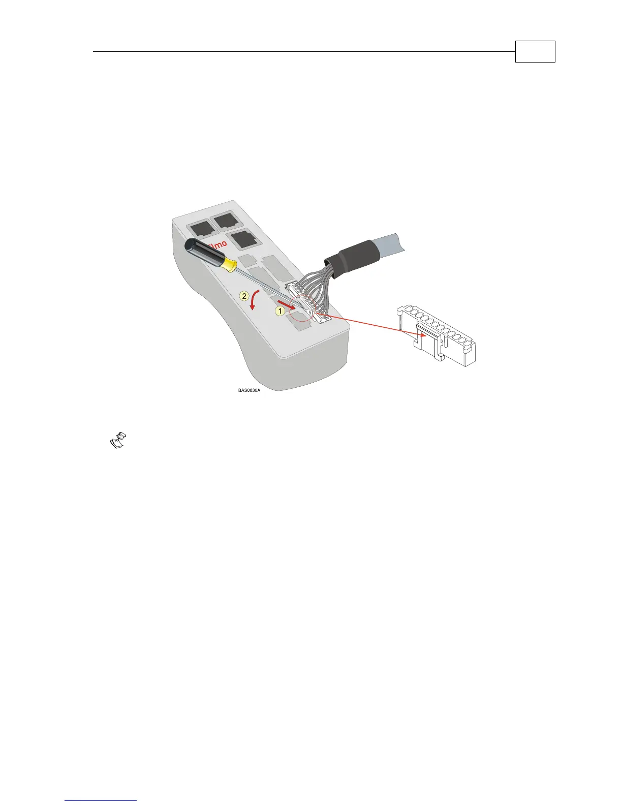
J7) all use 2 mm pitch Molex “Sherlock” connectors. These connectors snap together quite
easily, but require a small standard screwdriver for disassembly. To disassemble the Molex
connector simply (1) slip the screwdriver into the lock (this will cause the lock to disengage)
and (2) twist the screwdriver downward with light pressure on the handle (see the figure
below).
Figure 3-8: Disconnecting Molex Connectors
Notes for assembling Feedback and Control cable assemblies:
Use 24 or 26 AWG twisted-pair shielded cables.
On the motor side connections, ground the shield to the motor chassis.
On controller side connections, follow the controller manufacturer’s
recommendations concerning shield and/or drain wire connections.
Bassoon Installation Guide Installation
MAN-BASIG (Ver 1.4)
3-12