3.5.7.2 Digital Output (Port J6)
Notes for connecting the digital output cable:
Use 24 or 26 AWG twisted pair shielded cable.
Connect the cable shield to the ground near the controller according to the
manufacturer’s recommendations.
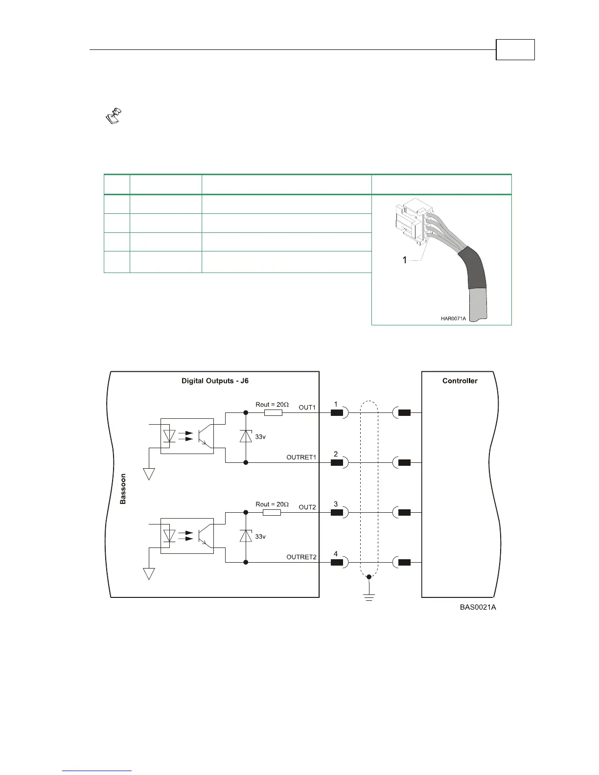
Pin Signal Function Pin Position
1 OUT1 Programmable output 1
2 OUTRET1 Programmable output return 1
3 OUT2 Programmable output 2
4 OUTRET2 Programmable output return 2
Table 3-13: Digital Output Cable Pin Assignment
Figure 3-25: Digital Output Connection Diagram
Bassoon Installation Guide Installation
MAN-BASIG (Ver 1.4)
3-30