3.5.7 I/O Cables
The following table lists the I/O cables that you should connect according to your specific
requirements:
I/O Description Total Port
Digital input 6 J5
Digital output 2 J6
Analog input 1 J7
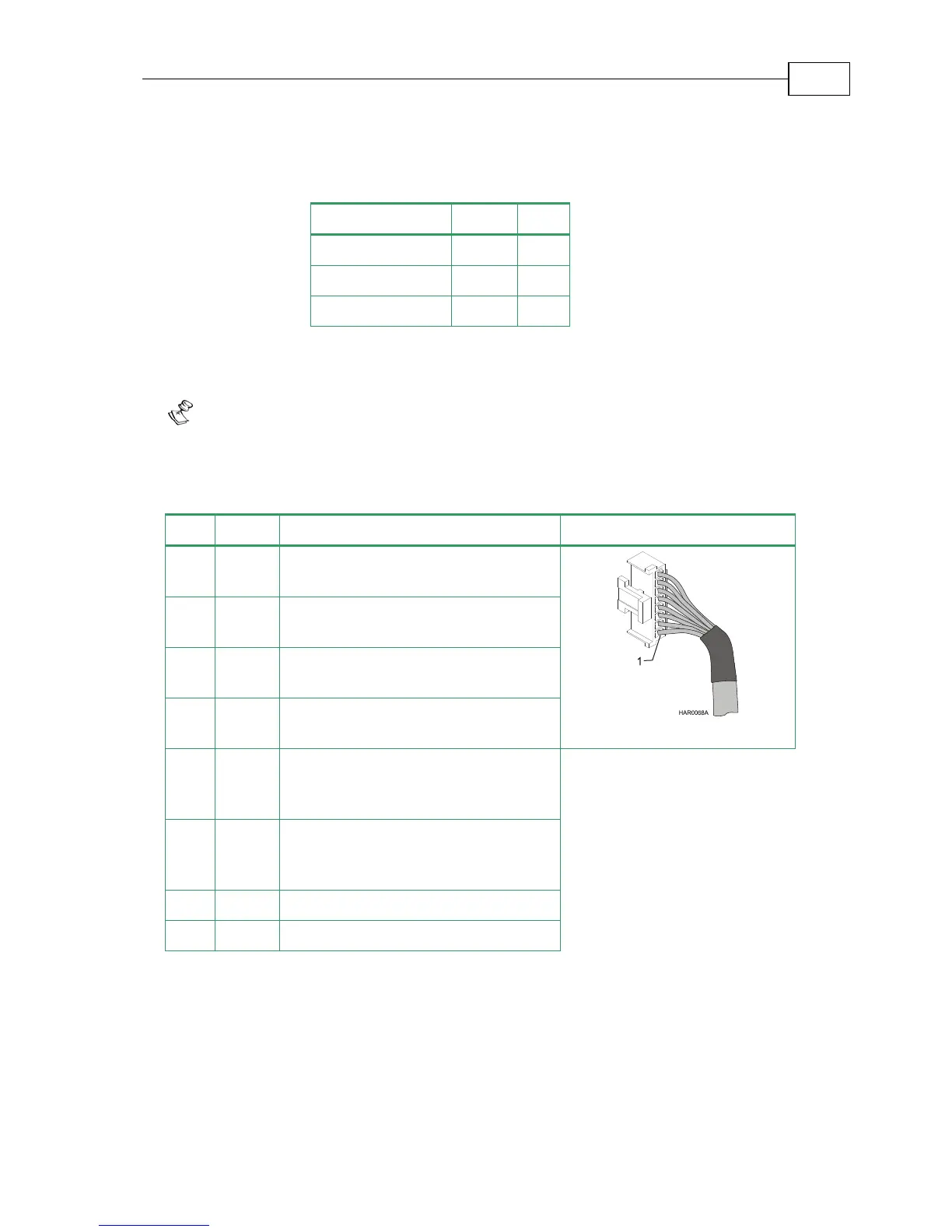
3.5.7.1 Digital Input (Port J5)
Notes for connecting the digital input cable:
Use 24 or 26 AWG twisted pair shielded cable.
Connect the cable shield to the ground near the signal source (controller)
according to the manufacturer’s recommendations.
Pin Signal Function Pin Position
1 IN1 Programmable input 1
(general purpose, RLS, FLS, INH)
2 IN2 Programmable input 2
(general purpose, RLS, FLS, INH)
3 IN3 Programmable input 3
(general purpose, RLS, FLS, INH)
4 IN4 Programmable input 4
(general purpose, RLS, FLS, INH)
5 IN5 Programmable input 5
(event capture, Main Home,
general purpose, RLS, FLS, INH)
6 IN6 Programmable input 6
(event capture, Auxiliary Home,
general purpose, RLS, FLS, INH)
7 INRET Programmable input return
8 INRET Programmable input return
Table 3-12: Digital Input Cable Pin Assignments
Bassoon Installation Guide Installation
MAN-BASIG (Ver 1.4)
3-28