Do you have a question about the ELNet LT and is the answer not in the manual?
Provides details on the ELNet LT Energy & Powermeter, its features, and benefits for users.
Explains how the manual is structured and intended for different user roles and how to navigate it.
Provides crucial safety warnings and precautions for operating and installing the ELNet LT Energy & Powermeter.
Outlines the warranty terms and conditions provided by CONTROL APPLICATIONS Ltd. for the ELNet LT Energy & Powermeter.
Invites user feedback for improving the manual and product information.
States the terms and conditions regarding information accuracy, changes, and liability for the manual and product.
Lists the items included in the ELNet LT Energy & Powermeter package.
Details the process and considerations for physically mounting the ELNet LT Energy & Powermeter.
Presents schematic diagrams for wiring the ELNet LT Energy & Powermeter in different configurations.
Explains the connections required on the rear panel of the ELNet LT Energy & Powermeter.
Describes the functionality and wiring of the digital output and input connections on the ELNet LT Energy & Powermeter.
Details how to access and interpret manufacturing information and system data for the ELNet LT Energy & Powermeter.
Provides an overview of the ELNet LT Energy & Powermeter's front panel, including its screen and control buttons.
Explains the functions and operation of the six control buttons located on the front panel of the ELNet LT Energy & Powermeter.
Describes how to lock and unlock the control buttons on the ELNet LT Energy & Powermeter to prevent unauthorized use.
Details the process of entering the technical code required to access and configure settings on the ELNet LT Energy & Powermeter.
Guides on how to set or change parameters for current and voltage transformers to ensure accurate measurements.
Explains the importance and procedure for performing an electrical connection check, including phase order verification.
Provides instructions on how to change the display language on the ELNet LT Energy & Powermeter.
Guides on how to set or adjust the internal clock time on the ELNet LT Energy & Powermeter.
Provides instructions on how to set or change the current date on the ELNet LT Energy & Powermeter.
Explains how to configure the digital output to function as an energy pulse output, defining pulse value and time.
Describes the different electrical network types (Delta, Open Delta, Star) that the ELNet LT can be installed in.
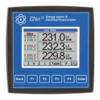
Details how to display and interpret current, voltage, and frequency readings for all three phases on the front panel.
Guides on how to clear old peak values for current, voltage, and frequency measurements on the ELNet LT Energy & Powermeter.
Explains the measurement of leakage current, its safety implications, and how the ELNet LT LTP model handles it.
Provides instructions to display real-time power readings (active, reactive, apparent) for all three phases.
Discusses power quality aspects including waveform display, harmonics analysis, and alarm setup.
Explains how to display waveform graphs for voltage and current, including line selection.
Details how to analyze and display harmonics bar graphs and THD values for voltage and current.
Guides on setting alarm levels for various electrical measurements like voltage, current, and demand.
Explains the structure and format of MODBUS frames used for data transmission with the ELNet LT Energy & Powermeter.
Details the RTU transmission mode for MODBUS, including parity options for communication setup.
Describes the components of an RTU MODBUS frame, including address, function, data, and check fields.
Explains the role of the address field in MODBUS communication, identifying each device on the network.
Details the function field in MODBUS, which specifies the type of action the powermeter should perform.
Describes the data field in a MODBUS message, containing instructions or information for the powermeter.
Explains the check field (CRC) in MODBUS, used for error detection in data transmission.
Discusses the MODBUS registers used by the ELNet LT Energy & Powermeter for data reading and writing.
Provides information on how to access and potentially change MODBUS register addresses for the ELNet LT Energy & Powermeter.
Details the physical connections required for RS485 communication on the ELNet LT Energy & Powermeter.
Outlines the necessary communication setup parameters on both the PC and the ELNet LT Energy & Powermeter for successful connection.
Explains the requirement for a unique communication address for each powermeter in a MODBUS network.
Describes the baud rate settings, which determine the communication speed between the ELNet LT Energy & Powermeter and the PC.
Explains the parity options (NONE or EVEN) for MODBUS serial communication setup.
Guides on configuring communication settings for the ELNet LT Energy & Powermeter, including serial communication.
Provides step-by-step instructions for setting up serial communication parameters for the ELNet LT Energy & Powermeter.
Guides on configuring Ethernet communication settings, including IP address, gateway, and mask for the ELNet LT Energy & Powermeter.
Explains how to use the UniArt software to read and write registers of the ELNet LT Energy & Powermeter.
Provides a detailed table of measurement parameters, their display ranges, and measuring limits for the ELNet LT Energy & Powermeter.
A checklist to ensure all installation and configuration steps for the ELNet LT Energy & Powermeter are completed correctly.
| Mounting | DIN Rail |
|---|---|
| Display | LCD |
| Protocols | Modbus RTU |
| Communication | RS485 |
| Accuracy | 0.5% |
| Operating Temperature | -10 to +55°C |