
A
Ashley ColeSep 12, 2025
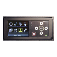
Why does my Eltek BC2000 Controller show Unknown System?
- HHeather LeeSep 12, 2025
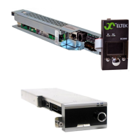
During new installation / turn up of the plant, if the Eltek Controller displays Unknown System, make sure at least one rectifier module is inserted in the shelf.