Cabling the Standby Power Supply to the SP serial ports
There are two SPSs in a VNX8000 system. The lower SPS is cabled to SP A and SP B here.
The second SPS will be cabled to the first DAE (DAE 0) in a later section. The VNX8000
has two types of SPS sense cables. One pair has RJ12 to Micro-DB9 connections. The
second pair has RJ12 to RJ12 connections. Be sure to identify the correct cables by the
cable labels and connectors.
These cables connect the two lowest components in the system. Because the SPE
extends farther into a cabinet than the SPS, connecting these cables may be difficult.
Procedure
1. Locate the cables shown in Figure 24 on page 40.
These cables have RJ12 connections on one end and a 9-pin mini-connector on the
other and have cable labels pre-attached.
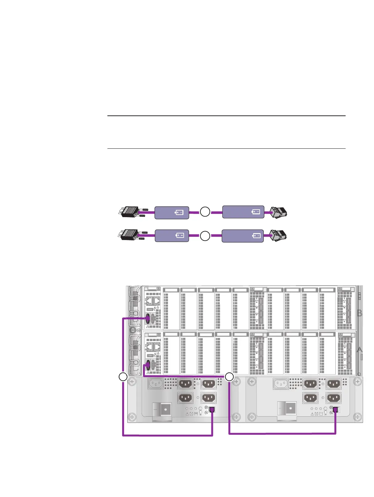
Figure 24 Cables connecting the SPE SPS to the SPE
SPS A SP
SPS B SP
SPE B
SPE A
2
1
2. Connect SPS A to SP A. See cable 1.
3. Connect SPS B to SP B. See cable 2.
Figure 25 Cabling to management ports on SPE and the SPE SPS
Cable your system
40 EMC VNX Series VNX8000 Block Installation Guide

 Loading...


