Procedure
1. Locate the sense cables shown in Figure 27 on page 42.
They are RS232 cables with a 6-pin modular plug on each end. These cables have the
cable labels pre-attached.
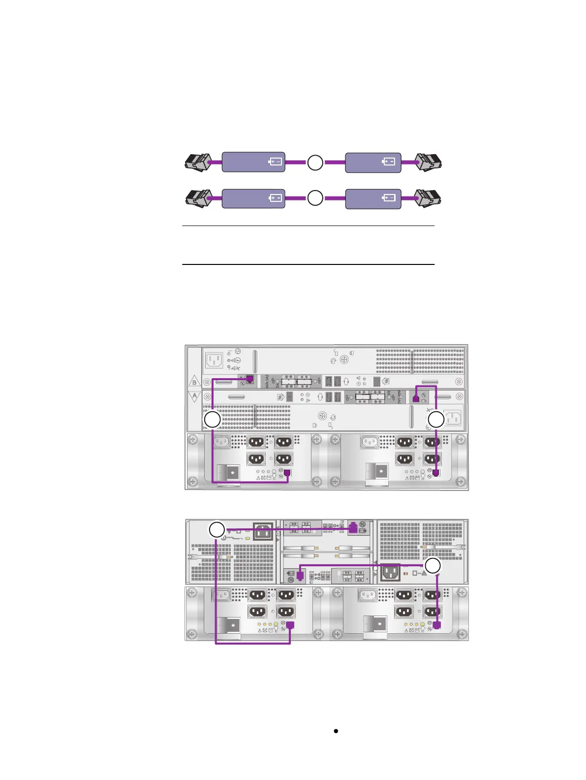
Figure 27 Cables connecting SPS to DAE 0
SPS A DAE
SPS B DAE
DAE 0 B
DAE 0 A
1
2
Identify these cables by the cable labels and the connectors.
2. Connect SPS A to LCC A of DAE 0. See cable 1.
3. Connect SPS B to LCC B of DAE 0. See cable 2.
See Figure 28 on page 42 for the cabling connections when DAE 0 is a 3U DAE. See
Figure 29 on page 42 for the cabling connections when DAE 0 is a 2U DAE.
Figure 28 Cabling between the SPS and 3U DAE 0
Figure 29 Cabling between the SPS and 2U DAE 0
Cabling the SPs to DAE 0
Cabling between the SPE and DAEs uses Serial Attached SCSI (SAS) cables. The cables
between the SPE ports and LCC ports on DAEs are 2-meter mini-SAS HD to mini-SAS. The
connectors on the mini-SAS end have a icon indicating the port for that end.
Cable your system
42 EMC VNX Series VNX8000 Block Installation Guide

 Loading...


