Connecting or verifying power cables
Before you begin
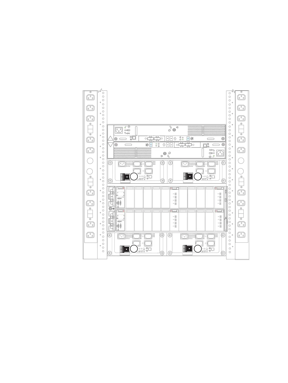
Ensure that all the switches for both the SPE SPS and the DAE 0 SPS are turned OFF:
locations 1, 2, 3, and 4 in Figure 34 on page 48.
Figure 34 Power up preparation
Ensure that all cabinet circuit breakers are in the ON position, all necessary PDU switches
are switched on, and power is connected.
The power cables are color-coded. Two colors identify the different zones (PDUs). Black
power cables connect to PDU B, while gray power cables connect to PDU A.
As soon as you connect the power cables, the component starts powering up
automatically. This is normal.
Connecting or verifying the gray power cables for PDU A
Procedure
1. Use the gray power cables to connect the PDU A side cables:
Refer to Figure 35 on page 49 while performing the procedure that follows.
2. Connect SPE SPS A to power distribution unit (PDU) A. See cable 1.
Power up
48 EMC VNX Series VNX8000 Block Installation Guide

 Loading...


