Figure 38 SPS LEDs (continued)
1 SPS A battery 4 SPS B tray
2 SPS A tray 5 SPS B color wheel latch indicator
l
Green = engaged
l
Yellow = parked
l
Red = not engaged or installed
3 SPS B battery 6 SPS A power on LED (Green)
Procedure
1. Verify that the power on LED on each SPS unit is green.
2. Verify that the color wheel latch indicator on each SPS unit is green.
Verify DAE 0 status
Ensure that DAE 0 powered up correctly by using the physical indicators on each
enclosure. The hardware information guide for your system provides more information on
all the LEDs.
Verify 3U, 15 3.5" drive DAE status
Procedure
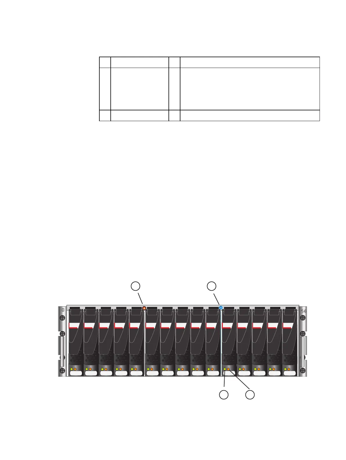
1. Verify that the status of the 3U DAE Power LED located on the front is solid blue and
the DAE Fault/Status LED is off as shown in Figure 39 on page 52.
2. If any fault LEDs are on, or if any power LEDs are flashing, contact your authorized
service provider.
Figure 39 3U, 15 3.5” drive DAE LEDs
SAS SAS SAS SAS SAS SAS SAS SAS SAS SAS SAS SAS SAS SAS SAS
1 2
3
4
Power up
52 EMC VNX Series VNX8000 Block Installation Guide

 Loading...


