DPSI RV Mini Family Operating Instructions Version 1.0
Page 11 of 54
In these examples, the outputs of the DPSI RV Mini are assigned to
the corresponding rudders. Outputs at the DPSI are labeled "Out 1/1",
"Out2", and so on.
Additional servos and auxiliaries can be directly connected to the
receiver.
Hint:
Assignment of the receiver channels to the DPSI is totally arbitrary and therefore
not stringent. Mapping according to the manufacturer (e.g. channel 1 = throttle,
etc.) is not necessary. Receiver channel 3 can be connected to DPSI input 1 just
as well. Any combination is allowed and possible.
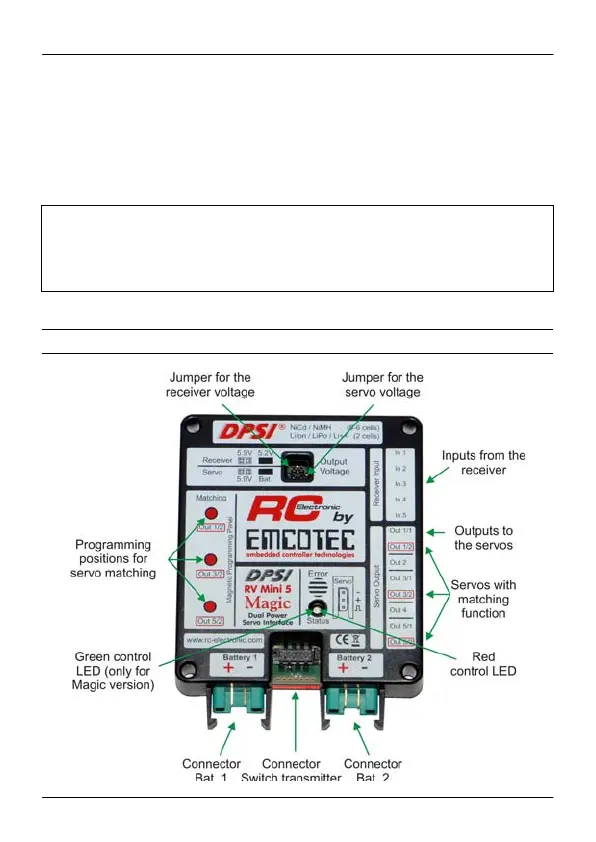
4. Overall layout