DPSI RV Mini Family Operating Instructions Version 1.0
Page 38 of 54
9.11. Connecting Servos
The DPSI RV Mini 5 (Magic) distributes 5 receiver channels to 8
servos in total (with 3 "built-in“ V-cables).
The DPSI RV Mini 6 (Magic) distributes 6 receiver channels to 7
servos in total (with 1 "built-in“ V-cable).
In the example at page 28, 8 servos are connected to the DPSI RV
Mini 5 in total, the throttle servo however directly at the receiver. For all
servos connected to the DPSI RV Mini the pulse wire points
downwards (as pretended by chamfered noses in housing). We do not
recommend connecting more than 10 servos in a receiver system
powered with a DPSI RV Mini in total because current limits can be
reached or thermal load could get too high.
Observe sufficient cooling when using digital servos, in any case.
Hint:
Dependent on number and force of servos total current consumption varies in the
system. The higher the total current consumption, the higher is the energy which
is converted to heat. The heat sink of the DPSI RV Mini can get very hot. This is
not an error, but rather represents normal function. Therefore, observe for
sufficient cooling (distance to neighboring walls like fuselage's side walls or
similar – eventually arrange for cooling air supply). On request, an additional heat
sink can be mounted.
Hint:
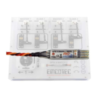
Printed assignment connections on top of the DPSI RV systems are only a
suggestion! Receiver channels may be connected to any DPSI inputs. Receiver
channel "1" might be connected to DPSI input "3". Servo outputs "3" of the DPSI
are then controlled by receiver channel "1". Assignment therefore is arbitrary!