DPSI RV Mini Family Operating Instructions Version 1.0
Page 27 of 54
9.5. Connecting the Receiver
Connect the receiver to the DPSI RV Mini using the delivered patch
cables (see print on housing). When connecting the receiver not all
inputs of the DPSI RV Mini must be used. Just connect as many
cables as needed. Each of the cables provides the receiver with
voltage.
Hint:
All receiver connection cables supply the receiver with regulated output voltage!
Therefore it is not relevant which cable (channel) is connected.
Hint:
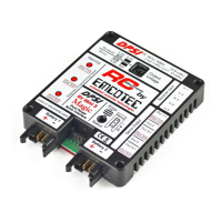
At all DPSI RV Mini systems the negative wire (brown) points to top i.e. towards
the print. The pulse wire (orange) points towards the heat sink.
Hint:
If the equipment does not work please make sure that all cables are correctly
connected and that the modulation mode of the transmitter corresponds to that of
the receiver (e.g. PPM, PCM, SPCM, IPD and so on).
Hint:
Assignment of the receiver channels on the DPSI housing's print is only a
suggestion! Assignment is arbitrary in any case. This means: receiver channel 1
must not necessarily be connected to channel 1 of the DPSI. It is only important
that servo outputs correspond to the receiver inputs of the DPSI (e.g. receiver
input 2 to servo output 2). Therefore, receiver channel 1 can be connected to
DPSI input 2. In this case servos at output 2 are controlled by receiver channel 1.
Hint:
Under no circumstances connect a patch-cable between receiver and a servo
output of the DPSI RV Mini. Both, the DPSI RV Mini or the receiver could
become damaged!