DPSI RV Mini Family Operating Instructions Version 1.0
Page 26 of 54
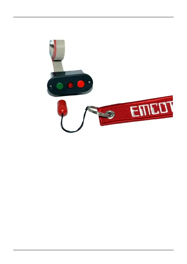
DPSI RV magnetically switch-actuator:
The central ultra bright LED in the switch actuator housing is lit when
the DPSI RV Mini is powered. In case of errors (e.g. low voltage) or
during programming, the LED indicates the states by different blink
codes.
Two commercially available battery controllers with JR-Uni connectors
can be connected directly at the rear of the switch actuator. The prints
"B1" and "B2" indicate battery 1 and battery 2 respectively. Herewith,
additional voltage monitoring is possible. When using such voltage
controllers, observe required cell numbers and/or correct battery type.
A turned off DPSI RV Mini system also turns off eventually connected
battery controllers, too.