Mentor MP Short Form Guide 29
Issue Number: 5 www.controltechniques.com
Safety Information Product information
Mechanical
installation
Electrical
installation
Getting started Running the motor
SMARTCARD
operation
Advanced
parameters
Diagnostics UL listing
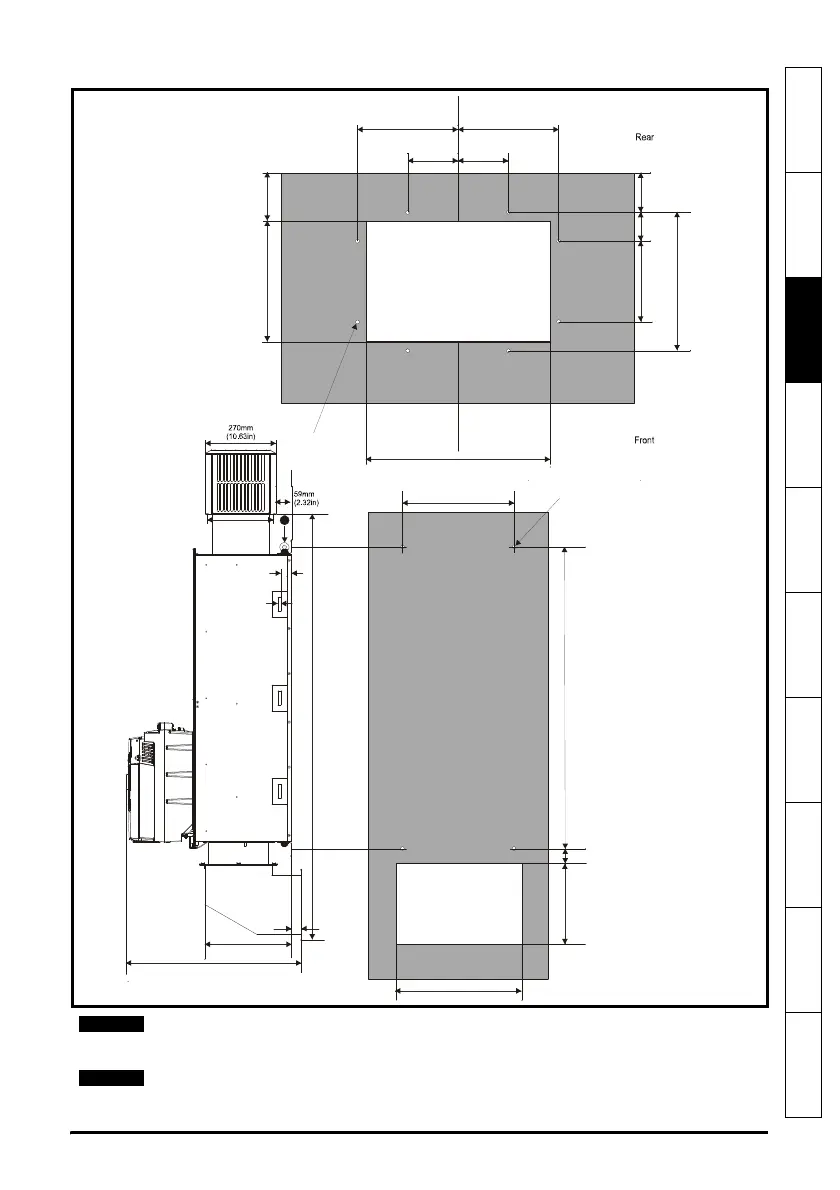
Figure 3-14 Size 2D back-plate and mounting detail
1. M10 eye-bolts can be inserted in the location shown for lifting the drive. These are
not supplied with the drive.
With the SMARTCARD installed to the drive, the depth measurement increases by 7.6
mm (0.30 in).
1065mm (41.93in)
288mm (11.34in)
260mm
(10.24in)
180mm (7.09in)
90mm
(3.54in)
90mm
(3.54in)
68.5mm
(2.70in)
50mm
(1.97in)
190mm
(7.48in)
240mm
(9.45in)
8 holes
∅
7mm
83.5mm
(3.29in)
210mm
(8.27in)
1
38mm
(1.5in)
9mm
(0.35in)

 Loading...

