Mentor MP Short Form Guide 33
Issue Number: 5 www.controltechniques.com
Safety Information Product information
Mechanical
installation
Electrical
installation
Getting started Running the motor
SMARTCARD
operation
Advanced
parameters
Diagnostics UL listing
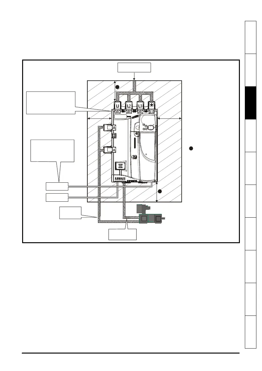
3.6 Enclosure
Enclosure layout
Please observe the clearances in the diagram below taking into account any
appropriate notes for other devices / auxiliary equipment when planning the installation.
Figure 3-19 Enclosure layout
3.7 Fan air flow data
Refer to section 3.7 in the Mentor MP User Guide.
External
controller
Ensure minimum clearances
are maintained for the drive.
Forced or convection air-flow
must not be restricted by any
object or cabling
Auxillary
supply
Signal cables
Plan for all signal cables
to be routed at least
300mm (12in) from the
drive and any power cable
Armature
connection
cable
Field
1) Power cabling must be at
least 100mm (4in) from the
drive in all directions
2) Ensure direct metal contact
at drive and filter mounting
points (any paint must be
removed)
100mm for Size 1 drives
200mm for Size 2A/2B drives
leave a clearance of 100mm

 Loading...

