Mentor MP Short Form Guide 35
Issue Number: 5 www.controltechniques.com
Safety Information Product information
Mechanical
installation
Electrical
installation
Getting started Running the motor
SMARTCARD
operation
Advanced
parameters
Diagnostics UL listing
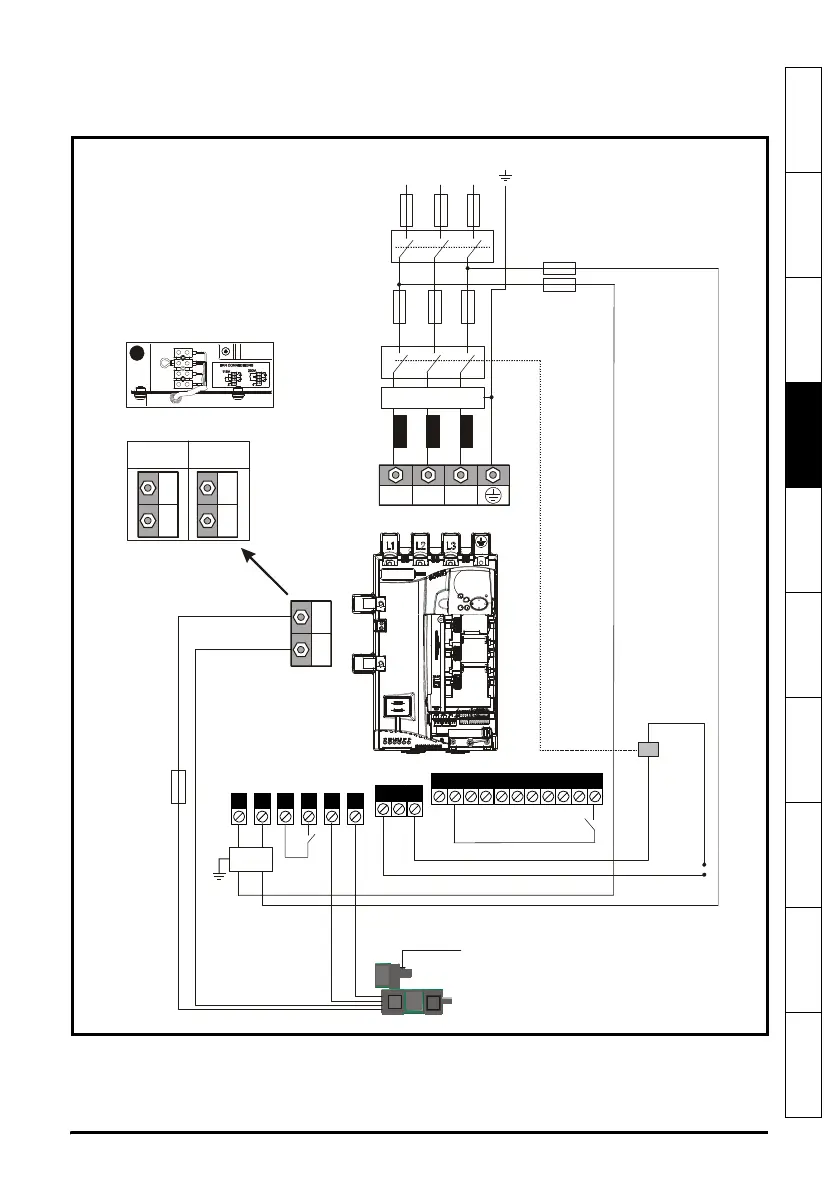
4.1 Electrical connections
Refer to Figure 4-1 to understand the function of the different power connections.
Figure 4-1 Power connections for 480V drive
1. End user must provide 230 / 115 Vac supply for the internal fans on frame sizes C and D, see
section 4.8 on page 58.
* For fuse ratings refer to section 4.6 Cable and fuse size ratings on page 41.
**For further information on EMC filters, please refer to the Mentor MP User Guide.
AC Supply
Semiconductor
fuses
L1 L2
L3
L1 L2 L3
Isolator
A1
A2
DC fuse
for 4Q only
Field
terminals
Armature
terminals
Auxiliary connections
Control connections
Motor
Fan supply (where applicable)
10A
10A
***
Branch
fuses
Branch
fuses
EMC
field
filter
**Optional EMC
armature filter
MA1
MA2
1
A1
A2 A1
A2
2 Quadrant
Drives
4 Quadrant
Drives

 Loading...

