Mentor MP Short Form Guide 63
Issue Number: 5 www.controltechniques.com
Safety Information Product information
Mechanical
installation
Electrical
installation
Getting started
Running the motor
SMARTCARD
operation
Advanced
parameters
Diagnostics UL listing
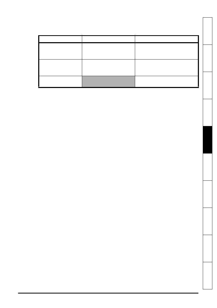
The SM-Keypad and the MP-Keypad can indicate when a SMARTCARD access is
taking place or when the second motor map is active (menu 21). These are indicated on
the displays as follows.
5.2 Keypad operation
Control buttons
The keypad consists of:
1. Joypad - used to navigate the parameter structure and change parameter values.
2. Mode button - used to change between the display modes – parameter view,
parameter edit, status.
3. Three control buttons - used to control the drive if keypad mode is selected. Refer to
the Mentor MP User Guide for further information.
4. Help button (MP-Keypad only) - displays text briefly describing the selected
parameter.
The Help button toggles between other display modes and parameter help mode. The
up and down functions on the joypad scroll the help text to allow the whole string to be
viewed. The right and left functions on the joypad have no function when help text is
being viewed.
The display examples in this section show the SM-Keypad, seven segment, LED
display. The examples are the same for the MP-Keypad, The exceptions is that the
information displayed on the lower row on the SM-Keypad is displayed on the right hand
side of the top row on the MP-Keypad.
SM-Keypad MP-Keypad
SMARTCARD access
taking place
The decimal point after the
fourth digit in the upper
display will flash.
The symbol ‘CC’ will appear in
the lower left hand corner of the
display
Second motor map
active
The decimal point after the
third digit in the upper
display will flash.
The symbol ‘Mot2’ will appear in
the lower left hand corner of the
display
Solutions Module
parameters displayed
The symbol ‘Opx’ will appear in
the left hand corner of the display

 Loading...

