Mentor MP Short Form Guide 61
Issue Number: 5 www.controltechniques.com
Safety Information Product information
Mechanical
installation
Electrical
installation
Getting started Running the motor
SMARTCARD
operation
Advanced
parameters
Diagnostics UL listing
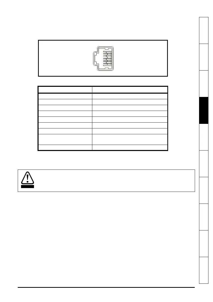
4.9.1 Serial communications connections
The Mentor MP has a serial communications port (serial port) as standard supporting
two wire EIA(RS)-485 communications.
Figure 4-9 Serial communications port
Table 4-22 RJ45 connections
The communications port applies a two-unit load to the communications network.
Connectors 2, 3, 7 and shield must always be made to the serial communications port.
Shielded cable must be used at all times.
Pin Function
1120 Ω Termination resistor
2RX TX
3 0V isolated
4+24V (100 mA)
5 0V isolated
6 TX enable
7RX\ TX\
8
RX\ TX\ (if termination resistors are
required, link to pin 1)
Shell 0V isolated
In order to meet the requirements for SELV in IEC 60950 (IT equipment) it is
necessary for the control computer to be grounded. Alternatively, when a lap-top or
similar device is used which has no provision for grounding, an isolation device must
be incorporated in the communications lead.

 Loading...

