Installation and commissioning PlasmaQuant MS product family
40
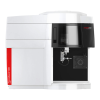
Fig. 18 Overview of connections on the right side of the instrument
Argon – sheath gas (optional, connection to the
transfer tube)
Argon – nebulizer gas
Interface to the spray chamber
5 Connection for water cooling (H
2
Connection for water cooling (H
2
O in)
Nebulizer gas
Cooling water connections to the spray chamber
The green standby switch is located on the front panel of the instrument. It controls
power flow between the power outlet and the power distribution module of the
instrument.
The standby switch and the circuit breaker on the rear side of the device must both be
in their ON position before the instrument can function.
On the front panel there is also an opening for possible coupling to accessories.
1 Opening for possible coupling to accessories
2
Standby switch
Fig. 19 Switches and connections on the front side of the instrument
The electrical connection data can be found on the type plate on the terminal strip.