3 Connection
General notes The Micropilot is a loop-powered transmitter with 4...20 mA analogue output and
superimposed HART signal. Note the following before connecting up:
•
The power supply rating must correspond to that on the nameplate.
•
Turn off the power before connecting up.
•
Connect the external ground terminal of the transmitter to the plant grounding
system before connecting up.
•
Always tighten the locking screw, since this connects the antenna to the ground
potential of the housing.
Hazardous areas If the measuring system is to be installed in a hazardous area, local regulations, national
guidelines and the specifications in the certificate are to be observed.The specified cable
gland must be used.
For certified transmitters, the explosion protection is realised as follows:
•
Housing F12: EEx ia.
The power supply must be intrinsically safe.
•
Housing T12: EEx e m.
The housing must be integrated into the plant grounding system.
The power must be switched off before the connection compartment is opened.
The electronics and current output are galvanically isolated from the antenna circuit.
Connection Connect up the Micropilot as follows:
•
Switch off power.
•
Unscrew lid of housing or connection compartment.
•
For F12 housing: If appropriate, remove VU 330.
Remove cover plate to connection compartment.
•
Pull out terminal module with plastic loop.
•
Thread cable through cable gland or conduit
•
Connect up, see wiring examples.
•
Push terminal module back into place.
•
For F12 housing: Screw cover plate to connection compartment
If appropriate, stow away VU 330.
•
Screw on housing or connection compartment lid and screw cable gland or
conduit tight.
•
Switch on power.
Caution!
1
2
3
4
–
+
–
+
1
2
3
4
ENDRESS+HAUSER
MICROPILOT II
Order Code: FMR231-CEGGJ1A1A
Ser.-No.: PIZ0187
IP 65
EEx ia
Messbereich max. 20 m
Measuring range
PN max 15 bar
T max. 150°C
antenna
BZT G133
414J
T < 80°C
A
U 16...30 DC
4...20 mA
Cable gland
Nameplate
external
ground
terminal
Connection compartment
behind cover plate –
loosen screws
BA171Y23
2nd cable entry
Operating elements in
display compartment
ground
terminal
HousingT12Housing F12
2x cable entries
at the rear
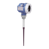
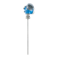
Fig. 3.1
Micropilot connection
compartments and nameplate
Warning!
Chapter 3 Connection Micropilot FMR 231
14 Endress+Hauser

 Loading...


