9 Technical Data
General information
Manufacturer Endress+Hauser
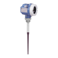
Instrument designation Micropilot FMR 231 E or FMR 231 A
Application
Continuous level measurement of liquids in tanks and stilling wells
Function and system design
Measurement prinicple Pulsed time-of-flight via microwave method (PTOF)
Evaluation Measuring cycle 2 Hz, evaluation with interference echo suppression.
Measurement updated once per second, depending upon evaluation mode.
Operating frequency Standard 5.8 GHz (ISM band), 6.3 GHz with FCC approval
Effective radiation power 1 µW EIRP (equivalent isotropic radiation power)
Beam angle approx. 23°
Modularity Compact loop-powered transmitter with integral antenna
Signal transmission 4...20mA and/or digital communication
Input
Measured variable Level, determined by the time-of-flight of a microwave pulse from transmitter
to product surface and back
Measuring range From antenna tip to 20 m from lower face of process connection;
zero and span adjustable
Output
Versions Analogue 4 – 20 mA output with superimposed HART digital signal
Output signal Analogue: useable output current range 3.8mA...20.5mA
Output resolution 10 bit (equivalent to 0.1% range end-value or microamps )
Load Housing F12: standard 0...1100 Ω EEx ia 0...820 Ω
Housing T12: standard 0...750 Ω EEx e 0...750 Ω
Min. load for HART communication 250 Ω
Signal on alarm Adjustable: MIN, MAX or HOLD; MIN = 3.8 mA, MAX=22.0 mA
Output damping Adjustable 0 – 250 s
Accuracy
Reference conditions Free-space reflection from flat metal surface, ambient temperature 25°C,
atmospheric pressure, output scaled to full measuring range
Linearity error Range up to 10 m: ±15 mm, from 10 m to 20 m: ±0.15% of range end-value
Resolution Analogue resolution better than 0.1% (10 µA)
Digital resolution: 1 mm
Repeatibility ±5 mm
Settling time ≤ 2s
Warm-up time 30 s
Ambient temperature
effect
±0.07%/10K of range end-value
Process pressure effect Process presssure 1 bar 16 bar 40 bar
20°C 0% –0.4% –1.2% of value
150°C 0% –0.2% –0.6% of value
Output load effect ±0.02%/100 Ω for changing load (negligible after re-calibration)
Operating conditions
Installation
Orientation Vertical; top-mounted
Position Where possible, minimum 30 cm from wall or structural element with free
beam path to process medium. Avoid mounting over filling streams.
No restrictions for stilling wells and bypass pipes.
Alignment marks parallel to tank wall.
Micropilot FMR 231 Chapter 9 Technical Data
Endress+Hauser 49
 Loading...


