2.2 Mounting in stilling wells
Installation
Mount the antenna perpendicular and in
the centre of the well.
•
Slight unevenness of the well surface or
light build-up do not influence the
measurement
•
Measurements also possible through
open ball valves.
•
The alignment mark to be found on the
flange should point towards the slots.
•
After mounting, the housing can be
turned through 350° for convenient
access to the display and connection
compartment. The locking screw must
be loosened before turning.
•
Tighten the locking screw after turning.
.
Stilling well design
To ensure highest accuracy, the stilling well
should be designed as follows.
•
Metal construction
•
Constant diameter.
•
If possible, welding seam along axis of
slots.
•
Slots offset at 180° (not 90°), deburred
•
Slot width max. 1/10 of pipe diameter.
The length and number of slots has no
effect on the measurement.
Ambient temperature
The ambient temperature of the housing
must be within the following limits, see also
Chapter 9.
•
Housing F12:
standard operation: –40°C...80°C
EEx ia T6 –40°C...50°C*
•
Housing T12:
standard operation: –40°C...80°C
EEx e T6 –40°C...50°C*
*For full details see certificate.
A protective cover is available for outdoor
mounting, Part No. 543199-0001.
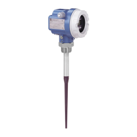
BA171Y77
inactive
length
100 mm
or
250 mm
locking screw
datum point for
measurement
alignment mark
pointing towards
the slots
spring
washer
for
cladded
flange
beam
launched
here
ground terminal
max. level
 Loading...


