Do you have a question about the Endress+Hauser FMR 231 and is the answer not in the manual?
Guide to calibrating with VU 330 or remote access for tanks.
Steps to verify correct installation of the device in the tank.
Procedures for calibrating the device for accurate measurements.
Assessing the quality of the received echo signals for reliable measurement.
Details of software version 1.0, its features and changes.
Details of software version 2.0, improvements and changes from previous versions.
Specifies the intended applications and operating conditions for the device.
General guidelines for safe installation, commissioning, and operation.
Safety requirements and certifications for operation in potentially explosive environments.
Compliance information regarding FCC regulations for device operation.
Explains symbols and conventions used throughout the manual for safety emphasis.
Details symbols and requirements related to explosion protection classifications.
Defines standard electrical symbols used in diagrams and connections.
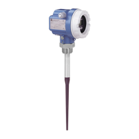
Describes the primary applications for the Micropilot FMR 231 level transmitter.
Outlines the different versions of the Micropilot FMR 231 based on configuration options.
Explains the time-of-flight microwave measurement technology used by the device.
Describes the type of measured variable and its acquisition process.
Details the output signal types and their correspondence to measurement values.
Specifies the device's measurement accuracy under reference conditions.
Defines the operational measuring ranges based on product class and application.
Describes the system components and configurations for 4...20 mA with HART.
Detailed instructions for mounting the device in a tank.
Important general considerations for mounting and beam path.
Guidance on aligning the device for optimal signal reception.
Specifies the acceptable ambient temperature ranges for the device housing.
Recommended mounting positions to avoid interference and ensure measurement quality.
Considerations for nozzle diameter and length relative to the antenna.
Instructions for installing the device using a threaded process connection.
Procedures for mounting the device within a stilling well.
Recommendations for designing stilling wells for optimal measurement.
Acceptable ambient temperature ranges for the device housing.
Information on the optional protective cover for outdoor mounting.
Specific connection details for the F12 housing type.
Location and information found on the device nameplate.
Important preliminary steps before connecting the device.
Safety precautions and requirements for connecting in hazardous areas.
Illustrative wiring diagrams for typical applications and system integrations.
How to operate the device directly using its keys and display.
Description of the VU 330 module and its operating elements.
Using the device keys for operation when the VU 330 is not connected.
Navigating the operating matrix using the VU 330 module.
Methods for operating the device remotely via HART communication.
Using the HART handheld device for remote operation and configuration.
Using the Commuwin II software for device configuration and monitoring.
Details on connecting Commuwin II to the device.
Utilizing graphical aids within Commuwin II for configuration tasks.
Configuring the device offline using Commuwin II before installation.
Transferring configurations to and from the device using Commuwin II.
Setup requirements for performing calibration outside the tank.
Step-by-step guide for calibrating and suppressing false echoes using device keys.
Adjusting the empty and full calibration points after initial setup.
Securing device parameters by locking the operating keys.
Performing fundamental calibration for tanks, setting empty/full distances and application parameters.
Steps for basic calibration including simulation and parameter entry.
Methods to suppress unwanted echoes that interfere with level measurement.
Steps for handling cases where the detected echo is the true level echo.
Steps for handling cases where the detected echo is a false echo.
Evaluating the quality of echo signals to ensure measurement accuracy.
Notes on the device's behavior and output after calibration is complete.
Calibration procedures specific to bypass pipes and stilling wells.
Steps for basic calibration including microwave factor and application parameter entry.
Detailed procedures for suppressing false echoes in various modes.
Final state of the device after calibration and echo suppression procedures.
Adjusting the output signal to represent tank volume or weight.
Different modes for linearizing the measurement output.
Error messages and warnings that may occur during linearisation entry.
How to deactivate or delete a linearisation table.
Setting linear relationships for volume or weight based on maximum values.
Entering custom linearisation curves using value pairs.
Specific method for linearizing measurements in horizontal cylindrical tanks.
Procedure for creating a linearisation table using semi-automatic entry.
Configuring the 4-20 mA analogue output signal.
Parameters for output damping, safety alarm, and value scaling.
Practical example showing analogue output configuration settings.
Features to ensure safe and reliable operation, like window suppression and plausibility.
Example configuration of safety functions like delay on lost echo.
Securing device settings by locking or unlocking the operating matrix.
Reading various parameters and status information from the device.
Accessing communication-specific settings like Tag No. and units.
Understanding the device's self-monitoring system for alarms and warnings.
How the device behaves and displays information during an alarm state.
How the device behaves and displays information during a warning state.
Expected behavior of the analogue output during fault conditions.
Listing and explanation of error codes and their significance.
Systematic approach to diagnosing common measurement errors and their remedies.
Setting application parameters to optimize signal evaluation for specific conditions.
Steps to align the device for optimal echo quality and measurement accuracy.
Methods for suppressing false echoes to ensure accurate level detection.
Different modes for factory or customer-defined false echo suppression.
Options for recording echo suppression maps based on measurement scenarios.
Suppressing echoes from fittings within a defined zone below the antenna.
Steps for configuring window suppression and safety zone responses.
Checking the plausibility of measured values to detect potential overspill or errors.
Using the simulation function to test linearisation and analogue output.
Procedures for resetting device parameters to factory defaults.
Routine checks and cleaning procedures for the transmitter.
Procedures for exchanging the complete Micropilot or its electronic module.
Information and precautions for sending the transmitter for repair.
Guidelines for ordering and identifying spare parts for the device.
Procedures for ordering and applying modification nameplates.
Specifics for ordering spare housings, including order code requirements.
Basic manufacturer and instrument designation details.
Defines the intended applications for the device.
Details on measurement principle, frequency, and signal transmission.
Specifies measured variable and range.
Details output signal characteristics, resolution, and load.
Provides accuracy specifications including linearity, resolution, and repeatability.
Environmental and operational parameters like temperature and pressure effects.
Specifies operating temperature, storage, ingress protection, and climate class.
Information on housing material, terminal compartments, and process connections.
Details on keypad, display, and optional modules.
Supply voltage, consumption, and HART specifications.
Lists relevant certifications and approvals for the device.
Provides physical dimensions for different housing and connection types.
Graphical representations of permissible operating limits based on temperature and pressure.
Detailed breakdown of product structure codes for FMR 231E model.
Detailed breakdown of product structure codes for FMR 231A model.
Overview of the device's operating matrix for parameter configuration.
Mapping between HART menus and the device's operating matrix.
| Brand | Endress+Hauser |
|---|---|
| Model | FMR 231 |
| Category | Measuring Instruments |
| Language | English |