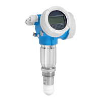
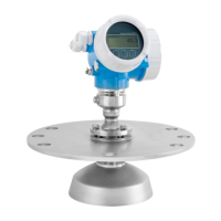
Micropilot FMR62
Endress+Hauser 15
Signal on alarm
Depending on the interface, failure information is displayed as follows:
• Current output
• Choice of failure mode (in accordance with NAMUR Recommendation NE 43):
Minimum alarm: 3.6 mA
Maximum alarm (= factory setting): 22 mA
• Failure mode with user-configurable value: 3.59 to 22.5 mA
• Local display
• Status signal (as per NAMUR Recommendation NE 107)
• Plain text display
• Operating tool via HART communication or service interface (CDI)
• Status signal (as per NAMUR Recommendation NE 107)
• Plain text display
Linearization
The device's linearization function allows the user to convert the measured value to any length or
volume units. Linearization tables for calculating the volume in cylindrical vessels are
preprogrammed into the device. Other linearization tables of up to 32 value pairs can be entered
manually or semi-automatically.
Galvanic isolation
All circuits for the outputs are galvanically isolated from each other.
Protocol-specific data HART
Manufacturer ID 17 (0x11)
Device type ID 0x112B
HART specification 7.0
Device description files (DTM, DD) Information and files under:
• www.endress.com
• www.fieldcommgroup.org
HART load min. 250 Ω
HART device variables The measured values can be freely assigned to the device variables.
Measured values for PV (primary variable)
• Level linearized
• Distance
• Electronic temperature
• Relative echo amplitude
• Area of incoupling
• Analog output adv. diagnostics 1
• Analog output adv. diagnostics 2
Measured values for SV, TV, QV (second, third and fourth variable)
• Level linearized
• Distance
• Electronic temperature
• Terminal voltage
• Relative echo amplitude
• Absolute echo amplitude
• Area of incoupling
• Analog output adv. diagnostics 1
• Analog output adv. diagnostics 2
Supported functions • Burst mode
• Additional transmitter status
Wireless HART data
Minimum starting voltage 17.5 V
Start-up current 4 mA
Starting time 80 s
Minimum operating voltage 17.5 V
 Loading...
