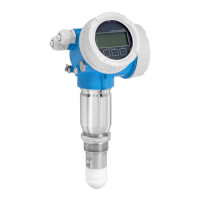
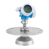
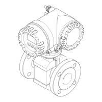
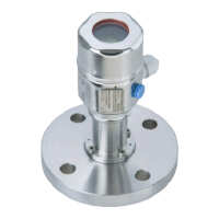
Micropilot FMR62
Endress+Hauser 33
Flange size Number of screws Tightening torque
DN100/PN16 8 40 to 60 Nm
DN150/PN16 8 75 to 115 Nm
ASME
2"/150lbs 4 40 to 55 Nm
3"/150lbs 4 65 to 95 Nm
3"/300lbs 8 40 to 55 Nm
4"/150lbs 8 45 to 70 Nm
4"/300lbs 8 55 to 80 Nm
6"/150lbs 8 85 to 125 Nm
6"/300lbs 12 999 to 999 Nm
JIS
10K 50A 4 40 to 60 Nm
10K 80A 8 25 to 35 Nm
10K 100A 8 35 to 55 Nm
10K 150A 8 75 to 115 Nm
Installation in stilling well
A0042912
15 Installation in stilling well
Measurements can be performed through an open full bore ball valve without any problems.
Recommendations for the stilling well
• Metal (no enamel liner; plastic liner on request)
• Constant diameter
• Stilling well not larger than antenna diameter
• Difference in diameter between antenna and inner diameter of the stilling well as small as possible
• Weld seam as even as possible
• Slot width or diameter of holes max. 1/10 of pipe diameter, deburred. The length and number do
not affect the measurement.
• Select an antenna that is as big as possible. Recommendation, use the 80mm/3" antenna.
• At transition points, e.g. when a ball valve is used or individual pipe segments are joined, any gaps
that occur should not exceed 1 mm (0.04 in).
• The inside of the stilling well must be smooth. Use an extruded or parallel-welded metal pipe as
the measuring pipe. The pipe can be extended with welding neck flanges or pipe sleeves. Flush-
align the flange and pipe properly on the inside.
• Do not weld through the pipe wall. The inside of the stilling well must remain smooth. If the pipe
is welded through unintentionally, carefully remove and smoothen any weld seams and
unevenness on the inside, as otherwise this will cause strong interference echoes and encourage
material buildup.
 Loading...
