OXY5500 Gas Analyzer Operating Instructions
Endress+Hauser 15
4.7.3 Protective chassis and ground connections
Before connecting any electrical signal or power, the protective and chassis grounds must be connected.
Requirements for the protective and chassis grounds are as follows:
• The protective and chassis grounds must be of equal or greater size than any other current-carrying conductors,
including the heater located in the sample conditioning system.
• The protective and chassis grounds must remain connected until all other wiring is removed.
• If the protective and chassis ground is insulated, it must use the green/yellow color.
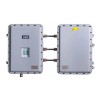
Refer to Figure 1 and Figure 2 for the protective and chassis ground locations.
4.7.4 Connecting electrical power to the analyzer
1. Open the OXY5500 analyzer electronics enclosure door. Take care not to disturb the electrical assembly inside.
Hazardous voltage and risk of electric shock. Failure to properly ground the analyzer may create a high-voltage
shock hazard.
2. Run conduit or armored braided cable from the power distribution panel to the conduit hub on the right side of
the analyzer enclosure labeled for power input.
Conduit seals or Ex e cable gland should be used where appropriate in compliance with local regulations.
Because the breaker in the power distribution panel or switch will be the primary means of disconnecting the
power from the analyzer, the power distribution panel should be located in close proximity to the equipment and
within easy reach of the operator, or within 3 meters (10 feet) of the analyzer.
The electrical installation to which the analyzer is connected must be protected against transients. The protective
device has to be set at a level not exceeding 140% of the peak rated voltage values at the power supply terminals.
An approved switch or circuit breaker rated for 15 amps should be used and clearly marked as the disconnecting
device for the analyzer.
3. For AC systems, pull ground, neutral (N), and L1 wires into the electronics enclosure. Refer to Figure 8.
For DC systems, pull VI +, – and ground wires into the electronics enclosure. Refer to Figure 8.
Figure 8. AC/DC power connections
4. Strip back the jacket and/or insulation of the wires just enough to connect to the power terminal block.
5. Connect the main ground wire to the protection ground terminal marked .
6. Close and tighten the analyzer enclosure door.
Apply 2.25 nm (20 in-lbs) of torque on each bolt to ensure the door is closed properly to maintain required
ingress protection.

 Loading...


