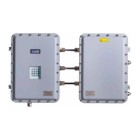
OXY5500 Gas Analyzer Operating Instructions
Endress+Hauser 83
8.9.3 Signal drift due to photo-decomposition
The oxygen-sensitive material may be subject to photo-decomposition resulting in a signal drift. Photo-
decomposition takes place only during illumination of the sensor tip and depends on the intensity of the excitation
light. Therefore, the excitation light should be minimized. Continuous illumination of a OP-3 oxygen sensor over a
period of 24 hours may lead to a phase drift of up to + 0.4% of reading at 20 °C. However, this effect of photo-
decomposition can be minimized by changing the measuring mode to the 30-second or minute interval mode. In
these modes, the software switches off the excitation light after recording the data point and switches it on after the
interval chosen. Use the interval method whenever possible to increase the operational life of the sensor. Refer to
Table 38 below.
Name Drift per 3600 Points Drift per 50000 Points Drift per 100000 Points
OP-3 <0.15% air-sat. <0.15% air-sat. <0.25% air-sat.
OP-6 <1 ppb <2 ppb < 3 ppb
Table 38. Sensor drift at zero reading (0 ppb) recording 3,600, 50,000 and 100,000 data points
8.10 Performance improvement
To improve the performance over past measurements, check the calibration values by using the calibration test gases
for “0” (UHP nitrogen 99.9999%), and the Span test gas (100 ppm oxygen/N2). This can be completed by using a
3-way valve connected to the test gas enabling the user to switch back and forth between bottles. This can assist in
verifying proper operation.
8.11 Troubleshooting
Refer to Table 39 for frequently asked questions related to troubleshooting the OXY5500 before contacting the
service department. To contact the service department, refer to “Service” in the next section.
Indication Suspected Cause Solution
No Sensor
detected!
Amplitude < 1000
Make sure that the SMA connector is connected
properly to the connector.
Signal too low! Amplitude < 3000 Check sensor connections or POF for any irregularities.
Refer to Low signal strength: High O2 on OP-3, OP-6, or
OP-9 probe → .
Signal Overflow!
Refer to High signal strength: Low O2 or no O2 on OP-
3, OP-6, or OP-9 probe → .
Critical Error 16! Reference signal exceeds specified range Refer to “Service”.
No Pt100! Pt100 sensor has wrong cable or is broken Check temperature sensor connection.
Critical Error 512! Measurement system defect Refer to “Service”.
SD Card Error! SD card cannot be read or it cannot be written on Refer to “Service”.
Pressure Sensor
out of range!
Pressure sensor is either not connected or provides
a current less than 4mA or higher than 20mA
Check the pressure sensor and its connection.
Flash Error! Writing on Flash was not successful Refer to “Service”.
Storage space full!
No more measurement files can be created and no
more measurement entries can be saved.
Delete measurement files via Measurement Browser or
Service Software.
Table 39. Potential instrument problems and their solutions
8.12 Service
For Service, refer to our website (https://endress.com/contact) for the list of local sales channels in your area.
To return the unit for service or replacement, refer to "Service repair order".

 Loading...


