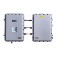
OXY5500 Gas Analyzer Operating Instructions
Endress+Hauser 75
8.5 Replacing the electro-optical module
Use the following procedure to replace and install the electro-optical module in the OXY5500 analyzer.
Photographs shown in this instruction are used to provide a clearer illustration of the required steps only. DO
NOT REMOVE the base plate from the analyzer enclosure to complete this instruction.
8.5.1 Required tools and hardware
• Flathead screwdriver
• Philips screwdriver
• Electro-optical module (P/N EX0800000020)
8.5.2 Removing the electro-optical module
1. Turn off power to the analyzer and open the enclosure door using a standard flathead screwdriver to unlatch the
lock.
2. Disconnect the ribbon cable from the keypad and set aside.
3. Disconnect the probes, power supply, and pressure sensor from the terminal blocks, as necessary. Refer to
Installation → .
4. Insert a flathead screwdriver in the clip extension at the top of the electro-optical module as shown in Figure 77.
Figure 77. Inserting screwdriver into clip extension
5. Press down on the corner of the electro-optical module and hold.
6. With the screwdriver, press down on the clip extension and away from the top of the module. Refer to Figure 78.
The electro-optical module should pop up.
Figure 78. Disconnecting the electro-optical module from the DIN rail

 Loading...


